Gear train
A gear train is a mechanical system formed by mounting gears on a frame so that the teeth of the gears engage.
Gear teeth are designed to ensure the pitch circles of engaging gears roll on each other without slipping, providing a smooth transmission of rotation from one gear to the next.[1]
The transmission of rotation between contacting toothed wheels can be traced back to the Antikythera mechanism of Greece and the south-pointing chariot of China. Illustrations by the Renaissance scientist Georgius Agricola show gear trains with cylindrical teeth. The implementation of the involute tooth yielded a standard gear design that provides a constant speed ratio.
Features of gears and gear trains include:
- The ratio of the pitch circles of mating gears defines the speed ratio and the mechanical advantage of the gear set.
- A planetary gear train provides high gear reduction in a compact package.
- It is possible to design gear teeth for gears that are non-circular, yet still transmit torque smoothly.
- The speed ratios of chain and belt drives are computed in the same way as gear ratios. See bicycle gearing.

Mechanical advantage
Gear teeth are designed so that the number of teeth on a gear is proportional to the radius of its pitch circle, and so that the pitch circles of meshing gears roll on each other without slipping. The speed ratio for a pair of meshing gears can be computed from ratio of the radii of the pitch circles and the ratio of the number of teeth on each gear.

The velocity v of the point of contact on the pitch circles is the same on both gears, and is given by

where input gear A has radius rA and meshes with output gear B of radius rB, therefore,

where NA is the number of teeth on the input gear and NB is the number of teeth on the output gear.
The mechanical advantage of a pair of meshing gears for which the input gear has NA teeth and the output gear has NB teeth is given by
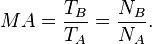
This shows that if the output gear GB has more teeth than the input gear GA, then the gear train amplifies the input torque. And, if the output gear has fewer teeth than the input gear, then the gear train reduces the input torque.
If the output gear of a gear train rotates more slowly than the input gear, then the gear train is called a speed reducer. In this case, because the output gear must have more teeth than the input gear, the speed reducer amplifies the input torque.
Analysis using virtual work
For this analysis, we consider a gear train that has one degree-of-freedom, which means the angular rotation of all the gears in the gear train are defined by the angle of the input gear.
The size of the gears and the sequence in which they engage define the ratio of the angular velocity ωA of the input gear to the angular velocity ωB of the output gear, known as the speed ratio, or gear ratio, of the gear train. Let R be the speed ratio, then

The input torque TA acting on the input gear GA is transformed by the gear train into the output torque TB exerted by the output gear GB. If we assume, that the gears are rigid and that there are no losses in the engagement of the gear teeth, then the principle of virtual work can be used to analyze the static equilibrium of the gear train.
Let the angle θ of the input gear be the generalized coordinate of the gear train, then the speed ratio R of the gear train defines the angular velocity of the output gear in terms of the input gear, that is

The formula for the generalized force obtained from the principle of virtual work with applied torques yields[2]
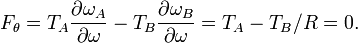
The mechanical advantage of the gear train is the ratio of the output torque TB to the input torque TA, and the above equation yields

Thus, the speed ratio of a gear train also defines its mechanical advantage. This shows that if the input gear rotates faster than the output gear, then the gear train amplifies the input torque. And, if the input gear rotates slower than the output gear, then the gear train reduces the input torque.
See also
- Machine (mechanical)
- Mechanism (engineering)
- Powertrain
- Wheel train (horology)
References
| ||||||||||||||||||||||||||||||||