GPS signals
| Geodesy | ||||||||||||||||
|---|---|---|---|---|---|---|---|---|---|---|---|---|---|---|---|---|
| Fundamentals | ||||||||||||||||
| Concepts | ||||||||||||||||
| Technologies | ||||||||||||||||
| Standards | ||||||||||||||||
|
||||||||||||||||
| History | ||||||||||||||||


Global Positioning System (GPS) satellites broadcast microwave signals to enable GPS receivers on or near the Earth's surface to determine location and synchronized time. The GPS system itself is operated by the U.S. Department of Defense (DoD) for use by both the military and the general public.
GPS signals include ranging signals, used to measure the distance to the satellite, and navigation messages. The navigation messages include ephemeris data, used to calculate the position of each satellite in orbit, and information about the time and status of the entire satellite constellation, called the almanac.
Legacy GPS signals
The original GPS design contains two ranging codes: the Coarse/Acquisition (C/A) code, which is freely available to the public, and the restricted Precision (P) code, usually reserved for military applications.
Coarse/Acquisition code
The C/A code is a 1,023 bit deterministic sequence called pseudorandom noise (also pseudorandom binary sequence) (PN or PRN code) which, when transmitted at 1.023 megabits per second (Mbit/s), repeats every millisecond. These sequences only match up, or strongly correlate, when they are exactly aligned. Each satellite transmits a unique PRN code, which does not correlate well with any other satellite's PRN code. In other words, the PRN codes are highly orthogonal to one another. This is a form of code division multiple access (CDMA), which allows the receiver to recognize multiple satellites on the same frequency.
Precision code
The P-code is also a PRN; however, each satellite's P-code PRN code is 6.1871 × 1012 bits long (6,187,100,000,000 bits, ~720.213 gigabytes) and only repeats once a week (it is transmitted at 10.23 Mbit/s). The extreme length of the P-code increases its correlation gain and eliminates any range ambiguity within the Solar System. However, the code is so long and complex it was believed that a receiver could not directly acquire and synchronize with this signal alone. It was expected that the receiver would first lock onto the relatively simple C/A code and then, after obtaining the current time and approximate position, synchronize with the P-code.
Whereas the C/A PRNs are unique for each satellite, the P-code PRN is actually a small segment of a master P-code approximately 2.35 × 1014 bits in length (235,000,000,000,000 bits, ~26.716 terabytes) and each satellite repeatedly transmits its assigned segment of the master code.
To prevent unauthorized users from using or potentially interfering with the military signal through a process called spoofing, it was decided to encrypt the P-code. To that end the P-code was modulated with the W-code, a special encryption sequence, to generate the Y-code. The Y-code is what the satellites have been transmitting since the anti-spoofing module was set to the "on" state. The encrypted signal is referred to as the P(Y)-code.
The details of the W-code are kept secret, but it is known that it is applied to the P-code at approximately 500 kHz,[1] which is a slower rate than that of the P-code itself by a factor of approximately 20. This has allowed companies to develop semi-codeless approaches for tracking the P(Y) signal, without knowledge of the W-code itself.
Navigation message
GPS message format Subframes Words Description 1 1–2 Telemetry and handover words
(TLM and HOW)3–10 Satellite clock,
GPS time relationship2/3 1–2 Telemetry and handover words
(TLM and HOW)3–10 Ephemeris
(precise satellite orbit)4/5 1–2 Telemetry and handover words
(TLM and HOW)3–10 Almanac component
(satellite network synopsis,
error correction)
In addition to the PRN ranging codes, a receiver needs to know detailed information about each satellite's position and the network. The GPS design has this information modulated on top of both the C/A and P(Y) ranging codes at 50 bit/s and calls it the Navigation Message.
The navigation message is made up of three major components. The first part contains the GPS date and time, plus the satellite's status and an indication of its health. The second part contains orbital information called ephemeris data and allows the receiver to calculate the position of the satellite. The third part, called the almanac, contains information and status concerning all the satellites; their locations and PRN numbers.
Whereas ephemeris information is highly detailed and considered valid for no more than four hours, almanac information is more general and is considered valid for up to 180 days. The almanac assists the receiver in determining which satellites to search for, and once the receiver picks up each satellite's signal in turn, it then downloads the ephemeris data directly from that satellite. A position fix using any satellite can not be calculated until the receiver has an accurate and complete copy of that satellite's ephemeris data. If the signal from a satellite is lost while its ephemeris data is being acquired, the receiver must discard that data and start again.
The navigation message itself is constructed from a 1,500 bit frame, which is divided into five subframes of 300 bits each and transmitted at 50 bit/s. Each subframe, therefore, requires 6 seconds to transmit. Each subframe has the GPS time. Subframe 1 contains the GPS date (week number) and information to correct the satellite's time to GPS time, plus satellite status and health. Subframes 2 and 3 together contain the transmitting satellite's ephemeris data. Subframes 4 and 5 contain components of the almanac. Each frame contains only 1/25th of the total almanac; a receiver must process 25 whole frames worth of data to retrieve the entire 15,000 bit almanac message. At this rate, 12.5 minutes are required to receive the entire almanac from a single satellite.
The orbital position data, or ephemeris, from the navigation message is used to calculate precisely where the satellite was at the start of the message. A more sensitive receiver will potentially acquire the ephemeris data more quickly than a less sensitive receiver, especially in a noisy environment.[2]
Each subframe is divided into 10 words. It begins with a Telemetry Word (TLM), which enables the receiver to detect the beginning of a subframe and determine the receiver clock time at which the navigation subframe begins. The next word is the handover word (HOW), which gives the GPS time (actually the time when the first bit of the next subframe will be transmitted) and identifies the specific subframe within a complete frame.[3][4] The remaining eight words of the subframe contain the actual data specific to that subframe.
After a subframe has been read and interpreted, the time the next subframe was sent can be calculated through the use of the clock correction data and the HOW. The receiver knows the receiver clock time of when the beginning of the next subframe was received from detection of the Telemetry Word thereby enabling computation of the transit time and thus the pseudorange. The receiver is potentially capable of getting a new pseudorange measurement at the beginning of each subframe or every 6 seconds.
Almanac
The almanac, provided in subframes 4 and 5 of the frames, consists of coarse orbit and status information for each satellite in the constellation, an Ionospheric model, and information to relate GPS derived time to Coordinated Universal Time (UTC). Each frame contains a part of the almanac (in subframes 4 and 5) and the complete almanac is transmitted by each satellite in 25 frames total (requiring 12.5 minutes).[5] The almanac serves several purposes. The first is to assist in the acquisition of satellites at power-up by allowing the receiver to generate a list of visible satellites based on stored position and time, while an ephemeris from each satellite is needed to compute position fixes using that satellite. In older hardware, lack of an almanac in a new receiver would cause long delays before providing a valid position, because the search for each satellite was a slow process. Advances in hardware have made the acquisition process much faster, so not having an almanac is no longer an issue. The second purpose is for relating time derived from the GPS (called GPS time) to the international time standard of UTC. Finally, the almanac allows a single-frequency receiver to correct for ionospheric delay error by using a global ionospheric model. The corrections are not as accurate as augmentation systems like WAAS or dual-frequency receivers. However, it is often better than no correction, since ionospheric error is the largest error source for a single-frequency GPS receiver.
Data updates
Satellite data is updated typically every 24 hours, with up to 60 days data loaded in case there is a disruption in the ability to make updates regularly. Typically the updates contain new ephemerides, with new almanacs uploaded less frequently. The Control Segment guarantees that during normal operations a new almanac will be uploaded at least every 6 days.
Satellites broadcast a new ephemeris every two hours. The ephemeris is generally valid for 4 hours, with provisions for updates every 4 hours or longer in non-nominal conditions. The time needed to acquire the ephemeris is becoming a significant element of the delay to first position fix, because as the hardware becomes more capable, the time to lock onto the satellite signals shrinks; however, the ephemeris data requires 18 to 36 seconds before it is received, due to the low data transmission rate.
Frequency information
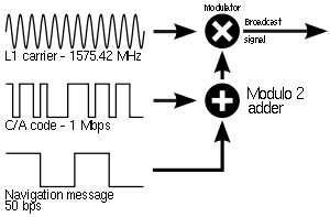
For the ranging codes and navigation message to travel from the satellite to the receiver, they must be modulated onto a carrier frequency. In the case of the original GPS design, two frequencies are utilized; one at 1575.42 MHz (10.23 MHz × 154) called L1; and a second at 1227.60 MHz (10.23 MHz × 120), called L2.
The C/A code is transmitted on the L1 frequency as a 1.023 MHz signal using a bi-phase shift keying (BPSK) modulation technique. The P(Y)-code is transmitted on both the L1 and L2 frequencies as a 10.23 MHz signal using the same BPSK modulation, however the P(Y)-code carrier is in quadrature with the C/A carrier (meaning it is 90° out of phase).
Besides redundancy and increased resistance to jamming, a critical benefit of having two frequencies transmitted from one satellite is the ability to measure directly, and therefore remove, the ionospheric delay error for that satellite. Without such a measurement, a GPS receiver must use a generic model or receive ionospheric corrections from another source (such as the Wide Area Augmentation System or WAAS). Advances in the technology used on both the GPS satellites and the GPS receivers has made ionospheric delay the largest remaining source of error in the signal. A receiver capable of performing this measurement can be significantly more accurate and is typically referred to as a dual frequency receiver.
Demodulation and decoding
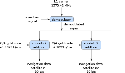
Since all of the satellite signals are modulated onto the same L1 carrier frequency, there is a need to separate the signals after demodulation. This is done by assigning each satellite a unique binary sequence known as a Gold code, and the signals are decoded, after demodulation, using modulo 2 addition of the Gold codes corresponding to satellites n1 through nk, where k is the number of channels in the GPS receiver and n1 through nk are the PRN identifiers of the satellites. Each satellite's PRN identifier is unique and in the range from 1 through 32.[6] The results of these modulo 2 additions are the 50 bit/s navigation messages from satellites n1 through nk. The Gold codes used in GPS are a sequence of 1,023 bits with a period of one millisecond. These Gold codes are highly mutually orthogonal, so that it is unlikely that one satellite signal will be misinterpreted as another. As well, the Gold codes have good auto-correlation properties.[7]
There are 1,025 different Gold codes of length 1,023 bits, but only 32 are used. These Gold codes are quite often referred to as pseudo random noise since they contain no data and are said to look like random sequences.[8] However, this may be misleading since they are actually deterministic sequences.
If the almanac information has previously been acquired, the receiver picks which satellites to listen for by their PRNs. If the almanac information is not in memory, the receiver enters a search mode and cycles through the PRN numbers until a lock is obtained on one of the satellites. To obtain a lock, it is necessary that there be an unobstructed line of sight from the receiver to the satellite. The receiver can then acquire the almanac and determine the satellites it should listen for. As it detects each satellite's signal, it identifies it by its distinct C/A code pattern.
The receiver uses the C/A Gold code with the same PRN number as the satellite to compute an offset, O, that generates the best correlation. The offset, O, is computed in a trial and error manner. The 1,023 bits of the satellite PRN signal are compared with the receiver PRN signal. If correlation is not achieved, the 1,023 bits of the receiver's internally generated PRN code are shifted by one bit relative to the satellite's PRN code and the signals are again compared. This process is repeated until correlation is achieved or all 1,023 possible cases have been tried.[9] If all 1,023 cases have been tried without achieving correlation, the frequency oscillator is offset to the next value and the process is repeated.
Since the carrier frequency received can vary due to Doppler shift, the points where received PRN sequences begin may not differ from O by an exact integral number of milliseconds. Because of this, carrier frequency tracking along with PRN code tracking are used to determine when the received satellite's PRN code begins.[9] Unlike the earlier computation of offset in which trials of all 1,023 offsets could potentially be required, the tracking to maintain lock usually requires shifting of half a pulse width or less. To perform this tracking, the receiver observes two quantities, phase error and received frequency offset. The correlation of the received PRN code with respect to the receiver generated PRN code is computed to determine if the bits of the two signals are misaligned. Comparisons of the received PRN code with receiver generated PRN code shifted half a pulse width early and half a pulse width late are used to estimate adjustment required.[10] The amount of adjustment required for maximum correlation is used in estimating phase error. Received frequency offset from the frequency generated by the receiver provides an estimate of phase rate error. The command for the frequency generator and any further PRN code shifting required are computed as a function of the phase error and the phase rate error in accordance with the control law used. The Doppler velocity is computed as a function of the frequency offset from the carrier nominal frequency. The Doppler velocity is the velocity component along the line of sight of the receiver relative to the satellite.
As the receiver continues to read successive PRN sequences, it will encounter a sudden change in the phase of the 1,023 bit received PRN signal. This indicates the beginning of a data bit of the navigation message.[11] This enables the receiver to begin reading the 20 millisecond bits of the navigation message. The TLM word at the beginning of each subframe of a navigation frame enables the receiver to detect the beginning of a subframe and determine the receiver clock time at which the navigation subframe begins. The HOW word then enables the receiver to determine which specific subframe is being transmitted.[3][4] There can be a delay of up to 30 seconds before the first estimate of position because of the need to read the ephemeris data before computing the intersections of sphere surfaces.
After a subframe has been read and interpreted, the time the next subframe was sent can be calculated through the use of the clock correction data and the HOW. The receiver knows the receiver clock time of when the beginning of the next subframe was received from detection of the Telemetry Word thereby enabling computation of the transit time and thus the pseudorange. The receiver is potentially capable of getting a new pseudorange measurement at the beginning of each subframe or every 6 seconds.
Then the orbital position data, or ephemeris, from the navigation message is used to calculate precisely where the satellite was at the start of the message. A more sensitive receiver will potentially acquire the ephemeris data more quickly than a less sensitive receiver, especially in a noisy environment.[2]
Modernization and additional GPS signals
Having reached full operational capability on July 17, 1995[12] the GPS system had completed its original design goals. However, additional advances in technology and new demands on the existing system led to the effort to "modernize" the GPS system. Announcements from the Vice President and the White House in 1998 heralded the beginning of these changes and in 2000, the U.S. Congress reaffirmed the effort, referred to as GPS III.
The project involves new ground stations and new satellites, with additional navigation signals for both civilian and military users, and aims to improve the accuracy and availability for all users. A goal of 2013 has been established with incentives offered to the contractors if they can complete it by 2011.
General features
Modernized GPS civilian signals have two general improvements over their legacy counterparts: a dataless acquisition aid and forward error correction (FEC) coding of the NAV message.
A dataless acquisition aid is an additional signal, called a pilot carrier in some cases, broadcast alongside the data signal. This dataless signal is designed to be easier to acquire than the data encoded and, upon successful acquisition, can be used to acquire the data signal. This technique improves acquisition of the GPS signal and boosts power levels at the correlator.
The second advancement is to use forward error correction (FEC) coding on the NAV message itself. Due to the relatively slow transmission rate of NAV data (usually 50 bits per second), small interruptions can have potentially large impacts. Therefore, FEC on the NAV message is a significant improvement in overall signal robustness.
L2C
One of the first announcements was the addition of a new civilian-use signal, to be transmitted on a frequency other than the L1 frequency used for the coarse/acquisition (C/A) signal. Ultimately, this became the L2C signal, so called because it is broadcast on the L2 frequency. Because it requires new hardware on board the satellite, it is only transmitted by the so-called Block IIR-M and later design satellites. The L2C signal is tasked with improving accuracy of navigation, providing an easy to track signal, and acting as a redundant signal in case of localized interference.
Unlike the C/A code, L2C contains two distinct PRN code sequences to provide ranging information; the Civilian Moderate length code (called CM), and the Civilian Long length code (called CL). The CM code is 10,230 bits long, repeating every 20 ms. The CL code is 767,250 bits long, repeating every 1500 ms. Each signal is transmitted at 511,500 bits per second (bit/s); however, they are multiplexed together to form a 1,023,000 bit/s signal.
CM is modulated with the CNAV Navigation Message (see below), whereas CL does not contain any modulated data and is called a dataless sequence. The long, dataless sequence provides for approximately 24 dB greater correlation (~250 times stronger) than L1 C/A-code.
When compared to the C/A signal, L2C has 2.7 dB greater data recovery and 0.7 dB greater carrier-tracking, although its transmission power is 2.3 dB weaker.
CNAV Navigation message
The CNAV data is an upgraded version of the original NAV navigation message. It contains higher precision representation and nominally more accurate data than the NAV data. The same type of information (Time, Status, Ephemeris, and Almanac) is still transmitted using the new CNAV format; however, instead of using a frame / subframe architecture, it features a new pseudo-packetized format made up of 12-second 300-bit message packets.
In CNAV, two out of every four packets are ephemeris data and at least one of every four packets will include clock data, but the design allows for a wide variety of packets to be transmitted. With a 32-satellite constellation, and the current requirements of what needs to be sent, less than 75% of the bandwidth is used. Only a small fraction of the available packet types have been defined; this enables the system to grow and incorporate advances.
There are many important changes in the new CNAV message:
- It uses forward error correction (FEC) in a rate 1/2 convolution code, so while the navigation message is 25 bit/s, a 50 bit/s signal is transmitted.
- The GPS week number is now represented as 13 bits, or 8192 weeks, and only repeats every 157.0 years, meaning the next return to zero won't occur until the year 2137. This is longer compared to the L1 NAV message's use of a 10-bit week number, which returns to zero every 19.6 years.
- There is a packet that contains a GPS-to-GNSS time offset. This allows for interoperability with other global time-transfer systems, such as Galileo and GLONASS, both of which are supported.
- The extra bandwidth enables the inclusion of a packet for differential correction, to be used in a similar manner to satellite based augmentation systems and which can be used to correct the L1 NAV clock data.
- Every packet contains an alert flag, to be set if the satellite data can not be trusted. This means users will know within 6 seconds if a satellite is no longer usable. Such rapid notification is important for safety-of-life applications, such as aviation.
- Finally, the system is designed to support 63 satellites, compared with 32 in the L1 NAV message.
L2C Frequency information
An immediate effect of having two civilian frequencies being transmitted is the civilian receivers can now directly measure the ionospheric error in the same way as dual frequency P(Y)-code receivers. However, if a user is utilizing the L2C signal alone, they can expect 65% more position uncertainty due to ionospheric error than with the L1 signal alone.[13]
Military (M-code)
A major component of the modernization process is a new military signal. Called the Military code, or M-code, it was designed to further improve the anti-jamming and secure access of the military GPS signals.
Very little has been published about this new, restricted code. It contains a PRN code of unknown length transmitted at 5.115 MHz. Unlike the P(Y)-code, the M-code is designed to be autonomous, meaning that a user can calculate their position using only the M-code signal. From the P(Y)-code's original design, users had to first lock onto the C/A code and then transfer the lock to the P(Y)-code. Later, direct-acquisition techniques were developed that allowed some users to operate autonomously with the P(Y)-code.
MNAV Navigation Message
A little more is known about the new navigation message, which is called MNAV. Similar to the new CNAV, this new MNAV is packeted instead of framed, allowing for very flexible data payloads. Also like CNAV it can utilize Forward Error Correction (FEC) and advanced error detection (such as a CRC).
M-code Frequency Information
The M-code is transmitted in the same L1 and L2 frequencies already in use by the previous military code, the P(Y)-code. The new signal is shaped to place most of its energy at the edges (away from the existing P(Y) and C/A carriers).
In a major departure from previous GPS designs, the M-code is intended to be broadcast from a high-gain directional antenna, in addition to a full-Earth antenna. This directional antenna's signal, called a spot beam, is intended to be aimed at a specific region (several hundred kilometers in diameter) and increase the local signal strength by 20 dB, or approximately 100 times stronger. A side effect of having two antennas is that the GPS satellite will appear to be two GPS satellites occupying the same position to those inside the spot beam. While the whole Earth M-code signal is available on the Block IIR-M satellites, the spot beam antennas will not be deployed until the Block III satellites are deployed, tentatively in 2013.
An interesting side effect of having each satellite transmit four separate signals is that the MNAV can potentially transmit four different data channels, offering increased data bandwidth.
The modulation method is binary offset carrier, using a 10.23 MHz subcarrier against the 5.115 MHz code. This signal will have an overall bandwidth of approximately 24 MHz, with significantly separated sideband lobes. The sidebands can be used to improve signal reception.
L5, Safety of Life
A civilian safety of life signal (broadcast in a frequency band protected by the ITU for aeronautical radionavigation service), first broadcast for demonstration purposes on satellite USA-203 (a Block IIR-M series satellite), and available on all GPS IIF satellites (and beyond).
Two PRN ranging codes are transmitted on L5: the in-phase code (denoted as the I5-code); and the quadrature-phase code (denoted as the Q5-code). Both codes are 10,230 bits long and transmitted at 10.23 MHz (1 ms repetition). In addition, the I5 stream is modulated with a 10-bit Neuman-Hoffman code that is clocked at 1 kHz and the Q5-code is modulated with a 20-bit Neuman-Hoffman code that is also clocked at 1 kHz.
- Improves signal structure for enhanced performance
- Higher transmitted power than L1/L2 signal (~3 dB, or 2× as powerful)
- Wider bandwidth provides a 10× processing gain
- Longer spreading codes (10× longer than C/A)
- Uses the Aeronautical Radionavigation Services band
L5 navigation message
The L5 CNAV data includes SV ephemerides, system time, SV clock behavior data, status messages and time information, etc. The 50 bit/s data is coded in a rate 1/2 convolution coder. The resulting 100 symbols per second (sps) symbol stream is modulo-2 added to the I5-code only; the resultant bit-train is used to modulate the L5 in-phase (I5) carrier. This combined signal is called the L5 Data signal. The L5 quadrature-phase (Q5) carrier has no data and is called the L5 Pilot signal.
L5 frequency information
Broadcast on the L5 frequency (1176.45 MHz, 10.23 MHz × 115), which is an aeronautical navigation band. The frequency was chosen so that the aviation community can manage interference to L5 more effectively than L2.[14]
L1C
Civilian use signal, broadcast on the L1 frequency (1575.42 MHz), which contains the C/A signal used by all current GPS users. The L1C will be available with the first Block III launch, scheduled for 2015.[15]
The PRN codes are 10,230 bits long and transmitted at 1.023 Mbit/s. It uses both Pilot and Data carriers like L2C.
The modulation technique used is BOC(1,1) for the data signal and TMBOC for the pilot. The time multiplexed binary offset carrier (TMBOC) is BOC(1,1) for all except 4 of 33 cycles, when it switches to BOC(6,1). Of the total L1C signal power, 25% is allocated to the data and 75% to the pilot.[16]
- Implementation will provide C/A code to ensure backward compatibility
- Assured of 1.5 dB increase in minimum C/A code power to mitigate any noise floor increase
- Data-less signal component pilot carrier improves tracking
- Enables greater civil interoperability with Galileo L1
CNAV-2 Navigation message
The L1C navigation message, called CNAV-2, is 1800 bits (including FEC) and is transmitted at 100 bit/s. It contains 9 bits of time information, 600 bits of ephemeris data, and 274 bits of packetized data payload.
Frequencies used by GPS
| Band | Frequency (MHz) |
Phase | Original usage | Modernized usage |
|---|---|---|---|---|
| L1 | 1575.42 (10.23×154) | In-phase (I) | Encrypted Precision P(Y) code | |
| Quadrature- phase (Q) | Coarse-acquisition (C/A) code | C/A, L1 Civilian (L1C), and Military (M) code | ||
| L2 | 1227.60 (10.23×120) | In-phase (I) | Encrypted Precision P(Y) code | |
| Quadrature- phase (Q) | Unmodulated carrier | L2 Civilian (L2C) code and Military (M) code | ||
| L3 | 1381.05 (10.23×135) | Used by Nuclear Detonation (NUDET) Detection System Payload (NDS); signals nuclear detonations/ high-energy infrared events. Used to enforce nuclear test ban treaties. | ||
| L4 | 1379.913 (10.23×1214/9) | (No transmission) | Being studied for additional ionospheric correction | |
| L5 | 1176.45 (10.23×115) | In-phase (I) | (No transmission) | Safety-of-Life (SoL) Data signal |
| Quadrature- phase (Q) | Safety-of-Life (SoL) Pilot signal | |||
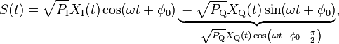
All satellites broadcast at the same two frequencies, 1.57542 GHz (L1 signal) and 1.2276 GHz (L2 signal). The satellite network uses a CDMA spread-spectrum technique where the low-bitrate message data is encoded with a high-rate pseudo-random (PRN) sequence that is different for each satellite. The receiver must be aware of the PRN codes for each satellite to reconstruct the actual message data. The C/A code, for civilian use, transmits data at 1.023 million chips per second, whereas the P code, for U.S. military use, transmits at 10.23 million chips per second. The L1 carrier is modulated by both the C/A and P codes, while the L2 carrier is only modulated by the P code.[17] The P code can be encrypted as a so-called P(Y) code which is only available to military equipment with a proper decryption key. Both the C/A and P(Y) codes impart the precise time-of-day to the user.
Each composite signal (in-phase and quadrature phase) becomes:
where  and
and  represent signal powers;
  and
and  represent codes with/without data
  .
.
See also
Sources and references
- ↑ US patent 5576715, Litton, James D.; Graham Russell & Richard K. Woo, "Method and apparatus for digital processing in a global positioning system receiver", issued 1996-11-19, assigned to Leica Geosystems
- ↑ 2.0 2.1 "AN02 Network Assistance". Retrieved 2007-09-10.
- ↑ 3.0 3.1 "NAVSTAR GPS User Equipment Introduction" (PDF). US Government. Retrieved 2013-07-24. Section 1.4.2.6.
- ↑ 4.0 4.1 "Essentials of Satellite Navigation Compendium"
- ↑ "Interface Specification IS-GPS-200, Revision D: Navstar GPS Space Segment/Navigation User Interfaces" (PDF). Navstar GPS Joint Program Office. Retrieved 2013-07-24. Page 103.
- ↑ "GPS Almanacs, NANUS, and Ops Advisories (including archives)". GPS Almanac Information. US Coast Guard. Retrieved 2009-09-09.
- ↑ "George, M., Hamid, M., and Miller A. Gold Code Generators in Virtex Devices PDF (126 KB)
- ↑ "GPS - explained (Signals)"
- ↑ 9.0 9.1 "How a GPS Receiver Gets a Lock". Gpsinformation.net. Retrieved 2009-10-13.
- ↑ "NAVSTAR GPS User Equipment Introduction" (PDF). US Government. Retrieved 2013-07-24. Section 1.4.2.4.
- ↑ "NAVSTAR GPS User Equipment Introduction" (PDF). US Government. Retrieved 2013-07-24. Section 1.4.2.5.
- ↑ US Coast Guard GPS FAQ
- ↑ "Interface Specification IS-GPS-200 Revision D" (PDF). United States Coast Guard. 7 December 2004. Retrieved 2010-07-18.
- ↑ "IS-GPS-705: NAVSTAR GPS Space Segment / User Segment L5 Interfaces" (PDF). United States Coast Guard. 22 September 2005. Retrieved 2010-07-18.
- ↑ "GPS III and OCX Satellite Launch, Early Orbit Ops Successfully Demonstrated". GPS World. GPS World. Retrieved 3 February 2014.
- ↑ "IS-GPS-800 Specification" (PDF). United States Coast Guard. 4 September 2008. Retrieved 2010-07-18.
- ↑ How GPS works. Konowa.de (2005).
| ||||||||||||||||||||||||||