Electrical reactance
In electrical and electronic systems, reactance is the opposition of a circuit element to a change in current or voltage, due to that element's inductance or capacitance. A built-up electric field resists the change of voltage on the element, while a magnetic field resists the change of current. The notion of reactance is similar to electrical resistance, but they differ in several respects.
An ideal resistor has zero reactance, whereas ideal inductors and capacitors have zero resistance – that is, respond to current only by reactance. The magnitude of the reactance of an inductor rises in proportion to a rise in frequency, while the magnitude of the reactance of a capacitor decreases in proportion to a rise in frequency (or increases in proportion to wavelength). As frequency goes up, inductive reactance goes up and capacitative reactance goes down.
Analysis
In phasor analysis, reactance is used to compute amplitude and phase changes of sinusoidal alternating current going through the circuit element. It is denoted by the symbol  .
.
Both reactance and resistance  are components of impedance
  .
.

where:
 is the impedance, measured in Ohms;
 is the resistance, measured in Ohms. It is the real part of the impedance:
 is the reactance, measured in Ohms. It is the imaginary part of the impedance:
 is the square root of minus one, usually represented by
  in non-electrical formulas. is used so as not to confuse the imaginary unit with current, commonly represented by .
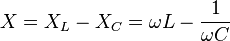
Both capacitive reactance  and inductive reactance
  contribute to the total reactance as follows.
where:
- is the capacitive reactance, measured in ohms;
- is the inductive reactance, measured in ohms;
 is the angular frequency,
  times the frequency in Hz.
Although and are both positive by convention, the capacitive reactance makes a negative contribution to total reactance.
Hence:
- if
 , the total reactance is said to be inductive;
 - if
 , then the impedance is purely resistive;
 - if
 , the total reactance is said to be capacitive.
Capacitive reactance
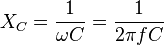
Capacitive reactance is an opposition to the change of voltage across an element. Capacitive reactance is inversely proportional to the signal frequency  (or angular frequency ω) and the capacitance
  .[1]
.[1]
A capacitor consists of two conductors separated by an insulator, also known as a dielectric.
At low frequencies a capacitor is open circuit, as no current flows in the dielectric. A DC voltage applied across a capacitor causes positive charge to accumulate on one side and negative charge to accumulate on the other side; the electric field due to the accumulated charge is the source of the opposition to the current. When the potential associated with the charge exactly balances the applied voltage, the current goes to zero.
Driven by an AC supply, a capacitor will only accumulate a limited amount of charge before the potential difference changes polarity and the charge dissipates. The higher the frequency, the less charge will accumulate and the smaller the opposition to the current.
Inductive reactance
Inductive reactance is an opposition to the change of current through an element. Inductive reactance is proportional to the sinusoidal signal frequency and the inductance  .
.

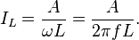
The average current flowing through an inductance in series with a sinusoidal AC voltage source of RMS amplitude  and frequency is equal to:
Because a square wave has multiple amplitudes at sinusoidal harmonics, the average current flowing through an inductance in series with a square wave AC voltage source of RMS amplitude and frequency is equal to:

making it appear as if the inductive reactance to a square wave was about five times larger:

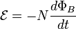
Any conductor of finite dimensions has inductance; the inductance is made larger by the multiple turns in an electromagnetic coil. Faraday's law of electromagnetic induction gives the counter-emf  (voltage opposing current) due to a rate-of-change of magnetic flux density
  through a current loop.

For an inductor consisting of a coil with  loops this gives.
The counter-emf is the source of the opposition to current flow. A constant direct current has a zero rate-of-change, and sees an inductor as a short-circuit (it is typically made from a material with a low resistivity). An alternating current has a time-averaged rate-of-change that is proportional to frequency, this causes the increase in inductive reactance with frequency.
Phase relationship
The phase of the voltage across a purely reactive device (a capacitor with an infinite resistance or an inductor with a resistance of zero) lags the current by  radians for a capacitive reactance and leads the current by radians for an inductive reactance. Without knowledge of both the resistance and reactance the relationship between voltage and current cannot be determined.
The origin of the different signs for capacitive and inductive reactance is the phase factor  in the impedance.
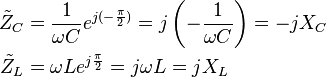
For a reactive component the sinusoidal voltage across the component is in quadrature (a phase difference) with the sinusoidal current through the component. The component alternately absorbs energy from the circuit and then returns energy to the circuit, thus a pure reactance does not dissipate power.
See also
References
- Shamieh C. and McComb G., Electronics for Dummies, John Wiley & Sons, 2011.
- Meade R., Foundations of Electronics, Cengage Learning, 2002.
- Pohl R. W. Elektrizitätslehre. – Berlin-Göttingen-Heidelberg: Springer-Verlag, 1960.
- Popov V. P. The Principles of Theory of Circuits. – M.: Higher School, 1985, 496 p. (In Russian).
- Küpfmüller K. Einführung in die theoretische Elektrotechnik, Springer-Verlag, 1959.
- Young, Hugh D.; Roger A. Freedman and A. Lewis Ford (2004) [1949]. Sears and Zemansky's University Physics (11 ed ed.). San Francisco: Addison Wesley. ISBN 0-8053-9179-7.
- ↑ Irwin, D. (2002). Basic Engineering Circuit Analysis, page 274. New York: John Wiley & Sons, Inc.
- ↑ http://hyperphysics.phy-astr.gsu.edu/hbase/hframe.html
External links
- Interactive Java Tutorial on Inductive Reactance National High Magnetic Field Laboratory
- Reactance calculator