Current transformer
A current transformer (CT) is used for measurement of alternating electric currents. Current transformers, together with voltage (or potential) transformers (VT or PT), are known as instrument transformers. When current in a circuit is too high to apply directly to measuring instruments, a current transformer produces a reduced current accurately proportional to the current in the circuit, which can be conveniently connected to measuring and recording instruments. A current transformer isolates the measuring instruments from what may be very high voltage in the monitored circuit. Current transformers are commonly used in metering and protective relays in the electrical power industry.
Design
Like any other transformer, a current transformer has a primary winding, a magnetic core and a secondary winding. The alternating current in the primary produces an alternating magnetic field in the core, which then induces an alternating current in the secondary winding circuit. An essential objective of current transformer design is to ensure the primary and secondary circuits are efficiently coupled, so the secondary current is linearly proportional to the primary current.
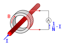
The most common design of CT consists of a length of wire wrapped many times around a silicon steel ring passed 'around' the circuit being measured. The CT's primary circuit therefore consists of a single 'turn' of conductor, with a secondary of many tens or hundreds of turns. The primary winding may be a permanent part of the current transformer, with a heavy copper bar to carry current through the magnetic core. Window-type current transformers (aka zero sequence current transformers, or ZSCT) are also common, which can have circuit cables run through the middle of an opening in the core to provide a single-turn primary winding. When conductors passing through a CT are not centered in the circular (or oval) opening, slight inaccuracies may occur.
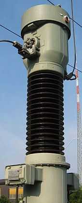
Shapes and sizes can vary depending on the end user or switchgear manufacturer. Typical examples of low-voltage single ratio metering current transformers are either ring type or plastic molded case. High-voltage current transformers are mounted on porcelain or polymer insulators to isolate them from ground. Some CT configurations slip around the bushing of a high-voltage transformer or circuit breaker, which automatically centers the conductor inside the CT window.
Current transformers can be mounted on the low voltage or high voltage leads of a power transformer; sometimes a section of bus bar is arranged to be easily removed for exchange of current transformers.
Usage

Current transformers are used extensively for measuring current and monitoring the operation of the power grid. Along with voltage leads, revenue-grade CTs drive the electrical utility's watt-hour meter on virtually every building with three-phase service and single-phase services greater than 200 amperes.
The CT is typically described by its current ratio from primary to secondary. Often, multiple CTs are installed as a "stack" for various uses. For example, protection devices and revenue metering may use separate CTs to provide isolation between metering and protection circuits, and allows current transformers with different characteristics (accuracy, overload performance) to be used for the devices.
The primary circuit is largely unaffected by the insertion of the CT. The rated secondary current is commonly standardized at 1 or 5 amperes. For example, a 4000:5 CT secondary winding will supply an output current of 5 amperes when the primary winding current is 4000 amperes. The secondary winding can be single or multi-ratio, with five taps being common for multi-ratio CTs.
The load, or burden, of the CT should be a low resistance. If the voltage time integral area is higher than the core's design rating, the core goes into saturation toward the end of each cycle, distorting the waveform and affecting accuracy.
Safety precautions
Care must be taken that the secondary of a current transformer is not disconnected from its load while current is in the primary, as the transformer secondary will attempt to continue driving current across the effectively infinite impedance up to its core saturation voltage. This may produce a high voltage across the open secondary into the range of several kilovolts, causing arcing, compromising operator and equipment safety, or permanently affect the accuracy of the transformer.
Accuracy
The accuracy of a CT is directly related to a number of factors including:
- Burden
- Burden class/saturation class
- Rating factor
- Load
- External electromagnetic fields
- Temperature and
- Physical configuration.
- The selected tap, for multi-ratio CTs
- Phase change
For the IEC standard, accuracy classes for various types of measurement are set out in IEC 61869-1, Classes 0.1, 0.2s, 0.2, 0.5, 0.5s, 1 and 3. The class designation is an approximate measure of the CT's accuracy. The ratio (primary to secondary current) error of a Class 1 CT is 1% at rated current; the ratio error of a Class 0.5 CT is 0.5% or less. Errors in phase are also important especially in power measuring circuits, and each class has an allowable maximum phase error for a specified load impedance.
Current transformers used for protective relaying also have accuracy requirements at overload currents in excess of the normal rating to ensure accurate performance of relays during system faults. A CT with a rating of 2.5L400 specifies with an output from its secondary winding of 20 times its rated secondary current (usually 5 A × 20 = 100 A) and 400 V (IZ drop) its output accuracy will be within 2.5 percent.
Burden
The secondary load of a current transformer is usually called the "burden" to distinguish it from the load of the circuit whose current is being measured.
The burden in a CT metering circuit is the (largely resistive) impedance presented to its secondary winding. Typical burden ratings for IEC CTs are 1.5 VA, 3 VA, 5 VA, 10 VA, 15 VA, 20 VA, 30 VA, 45 VA and 60 VA. ANSI/IEEE burden ratings are B-0.1, B-0.2, B-0.5, B-1.0, B-2.0 and B-4.0. This means a CT with a burden rating of B-0.2 can tolerate up to 0.2 Ω of impedance in the metering circuit before its secondary accuracy falls outside of an accuracy specification. These specification diagrams show accuracy parallelograms on a grid incorporating magnitude and phase angle error scales at the CT's rated burden. Items that contribute to the burden of a current measurement circuit are switch-blocks, meters and intermediate conductors. The most common source of excess burden is the conductor between the meter and the CT. When substation meters are located far from the meter cabinets, the excessive length of wire creates a large resistance. This problem can be reduced by using CTs with 1 ampere secondaries, which will produce less voltage drop between a CT and its metering devices.
Knee-point core-saturation voltage
The knee-point voltage of a current transformer is the magnitude of the secondary voltage above which the output current ceases to linearly follow the input current within declared accuracy. In testing, if a voltage is applied across the secondary terminals the magnetizing current will increase in proportion to the applied voltage, until the knee point is reached. The knee point is defined as the voltage at which a 10% increase in applied voltage increases the magnetizing current by 50%. For voltages greater than the knee point, the magnetizing current increases considerably even for small increments in voltage across the secondary terminals. The knee-point voltage is less applicable for metering current transformers as their accuracy is generally much higher, but constrained within a very small range of the current transformer rating, typically 1.2 to 1.5 times rated current. However, the concept of knee point voltage is very pertinent to protection current transformers, since they are necessarily exposed to fault currents of 20 to 30 times rated current.[1]
Phase shift
Ideally the secondary current of a current transformer should be perfectly in phase with the primary current. In practice, this is impossible to achieve, but phase shifts as low as a few tenths of a degree for well constructed transformers up to as much as six degrees for simpler designs may be encountered (for the normal power frequencies).[2] For the purposes of current measurement, any phase shift is immaterial as the indicating ammeter, only displays the magnitude of the current. However, if the current transformer is used in conjunction with the current circuit of a wattmeter, energy meter or power factor meter, any phase shift in the measured current can affect the accuracy of the target measurement. For power and energy measurement, this error is generally considered to be negligible at unity power factor but increases in significance as the power factor approaches zero. At true zero power factor, all the measured power is entirely due to the current transformer's phase error.[2] In recent years the introduction of electronic based power and energy meters has allowed the phase error to be calibrated out.[3]
Special designs
Specially constructed wideband current transformers are also used (usually with an oscilloscope) to measure waveforms of high frequency or pulsed currents within pulsed power systems. One type of specially constructed wideband transformer provides a voltage output that is proportional to the measured current. Another type (called a Rogowski coil) requires an external integrator in order to provide a voltage output that is proportional to the measured current. Unlike CTs used for power circuitry, wideband CTs are rated in output volts per ampere of primary current.
Standards
Ultimately, depending on client requirements, there are two main standards to which current transformers are designed. IEC 61869-1 (in the past IEC 60044-1) & IEEE C57.13 (ANSI), although the Canadian and Australian standards are also recognised.
High voltage types
Current transformers are used for protection, measurement and control in high-voltage electrical substations and the electrical grid. Current transformers may be installed inside switchgear or in apparatus bushings, but very often free-standing outdoor current transformers are used. In a switchyard, live tank current transformers have a substantial part of their enclosure energized at the line voltage and must be mounted on insulators. Dead tank current transformers isolate the measured circuit from the enclosure. Live tank CTs are useful because the primary conductor is short, which gives better stability and a higher short-circuit current rating. The primary of the winding can be evenly distributed around the magnetic core, which gives better performance for overloads and transients. Since the major insulation of a live-tank current transformer is not exposed to the heat of the primary conductors, insulation life and thermal stability is improved.
A high-voltage current transformer may contain several cores, each with a secondary winding, for different purposes (such as metering circuits, control, or protection).[4] A neutral current transformer is used as earth fault protection to measure any fault current flowing through the neutral line from the wye neutral point of a transformer.
See also
References
- Guile, A.; Paterson, W. (1977). Electrical Power Systems, Volume One. Pergamon. p. 331. ISBN 0-08-021729-X.
- ↑ Anon, Protective Relays Application Guide Second Edition, The General Electric Company Limited of England, 1975 Section 5.3
- ↑ 2.0 2.1 http://www.ccontrolsys.com/w/Measurement_Errors_Due_to_CT_Phase_Shift
- ↑ http://www.ccontrolsys.com/w/CT_Phase_Angle_Correction
- ↑ Protective Relays Application Guide, (The General Electric Company Limited of England, 1975) pages 78-87
External links
| Wikimedia Commons has media related to Current transformers. |