Constant fraction discriminator

A constant fraction discriminator (CFD) is an electronic signal processing device, designed to mimic the mathematical operation of finding a maximum of a pulse by finding the zero of its slope.
Some signals do not have a sharp maximum, but short rise times  .
.
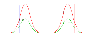
Typical input signals for CFDs are pulses from plastic scintillation counters, such as those used for lifetime measurement in positron annihilation experiments. The scintillator pulses have identical rise times that are much longer than the desired temporal resolution. This forbids simple threshold triggering, which causes a dependence of the trigger time on the signal's peak height, an effect called time walk (see diagram). Identical rise times and peak shapes permit triggering not on a fixed threshold but on a constant fraction of the total peak height, yielding trigger times independent from peak heights.
From another point of view

A time to digital converter assigns timestamps. The time to digital converter needs fast rising edges with normed height. The plastic scintillation counter delivers fast rising edge with varying heights. Theoretically, the signal could be split into two parts. One part would be delayed and the other low pass filtered, inverted and then used in a variable gain amplifier to amplify the original signal to the desired height. Practically, it is difficult to achieve a high dynamic range for the variable gain amplifier, and analog computers have problems with the inverse value.
Principle of operation
The incoming signal is split into three components.
One component is delayed by a time  , with
  - it may be multiplied by a small factor to put emphasis on the leading edge of the pulse -
and connected to the noninverting input of a comparator.
One component is connected to the inverting input of this comparator.
One component is connected to the noninverting input of another comparator.
A threshold value is connected to the inverting input of the other comparator.
The output of both comparators is fed through an AND gate.
Note from this description that a discriminator without that constant fraction would just be a comparator. Therefore the word discriminator is used for something different (namely for an FM-demodulator).
Note also that often the logic levels are shifted from -15 V < low < 0 < high < 15 V delivered by the comparator to 0 V < low < 1.5 V < high < 3.3 V needed by CMOS logic.
Applications
If the discriminator triggers a sampler with a following comparator this is called a single channel analyzer (SCA). If an Analog-to-digital converter is used, this is called a multi channel analyzer (MCA).
http://www.ortec-online.com/download/Fast-Timing-Discriminator-Introduction.pdf
References
- Beuzekom, M. (2006). "Identifying fast hadrons with silicon detectors", Appendix A, University of Groningen Faculty of Mathematics and Natural Sciences Dissertation