Constant-speed propeller
| Constant-speed propeller | |
|---|---|
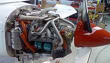
 Cutaway constant-speed propeller hub |
A constant-speed propeller is a variable-pitch propeller which automatically changes its blade pitch in order to maintain a chosen rotational speed. The power delivered is revs×torque, and the propeller operation places emphasis on torque. The operation better suits modern engines, particularly supercharged and gas turbine types.
Operation
An aircraft propeller operates as the source of thrust that moves the plane forward.
When an aircraft is stationary with the propeller spinning (in calm air), air flows past the narrow leading edge of the propeller. This is the most efficient configuration as the drag forces on the propeller are the lowest. As the airplane starts moving forward, the airflow begins to push against the front, wider cross section of the propeller, creating greater drag.
A constant-speed propeller is able to rotate along the longest axis of the blade to take a sharper bite of air with respect to the airplane, allowing the propeller to maintain the most efficient orientation to the airflow around it. This balances the tradeoff that fixed-pitch propellers must make between high take-off performance and high cruise performance.
A shallower angle of attack requires the least torque, but the highest RPM because the propeller is not moving very much air with each revolution. This is similar to a car operating in low gear. When the driver reaches cruising speed they will slow down the engine while still producing enough power to keep the vehicle moving. This is accomplished in an airplane by increasing the angle of attack of the propeller. This means that the propeller moves more air per revolution and allows the engine to spin slower while moving an equivalent volume of air, thus maintaining velocity.
The first attempts at constant-speed propellers were called counterweight propellers which were driven by mechanisms which operated on centrifugal force. Their operation is identical to the Watts governor used to limit the speed of steam and large diesel engines. A counterbalance was set up near or in the spinner, held in by a spring. When the propeller reached a certain RPM, centrifugal force would cause these counterbalances to swing outwards, which would drive a mechanism that twisted the propeller into a steeper pitch. When the airplane slowed down, the RPM would decrease enough for the spring to push the counterweights back in, realigning the propeller to the shallower pitch.
In newer models of constant-speed propellers, oil is pumped through the propeller shaft to push on a piston which drives the mechanism to change pitch. The flow of oil and the pitch is controlled by a governor, consisting of a speeder spring, fly weights, and a pilot valve. The tension of the speeder spring is set by the prop control lever, which sets the RPMs. The governor will maintain that RPM setting until an overspeed or underspeed condition exists. When an overspeed condition occurs, the propeller begins to rotate faster than the desired RPM setting. This would occur as the plane descends and airspeed increases. The fly weights begin to pull outward due to centrifugal force which further compresses the speeder spring. As that happens, the piston moves forward allowing the pilot valve to open and oil to flow from the oil sump into the hub. This increase in oil pressure will increase the pitch of the propeller angle causing it to slow back down to the desired RPM setting. When an underspeed condition occurs, as in a climb with loss of airspeed, just the opposite takes place. The airspeed decreases causing the propeller to slow down. This will cause the fly weights to move inward due to a lack in centrifugal force and tension will be released from the speeder spring. As this happens, the piston will move in the opposite direction causing the pilot valve to allow oil to flow from the hub back to the oil sump. The propeller blade angle will now decrease to a lower pitch allowing the propeller to speed back up to the desired RPM setting. This process usually takes place frequently throughout flight.
All high-performance propeller-driven aircraft have constant-speed propellers as they vastly improve fuel efficiency and performance, especially at high altitude.
Constant-speed units
A constant-speed unit (CSU) or propeller governor is the device fitted to one of these propellers to automatically change its pitch so as to attempt to keep engine speed constant. Most engines produce their maximum power in a narrow speed band. The CSU can be said to be to an aircraft what the CVT is to the motor car: the engine can be kept running at its optimum speed no matter what speed the aircraft is flying through the air. The advent of the CSU had another benefit: it allowed the designers of aircraft engines to keep ignition systems simple - the automatic spark advance seen in motor vehicle engines is simplified in aircraft engines.
Three methods are used to vary the pitch. Engine oil pressure is the usual mechanism used in commercial aircraft and the Continental and Lycoming engines fitted to light aircraft. Alternatively or additionally centrifugal weights may be attached directly to the propeller as in the Yak-52. Small modern engines such as the Rotax 912 which have a CSU may use either the traditional hydraulic method or an electrical pitch control mechanism. A pilot requires some additional training and, in most jurisdictions, a formal signoff before being allowed to fly aircraft fitted with a CSU. CSUs are not allowed to be fitted to aircraft certified under the USA Light-sport Aircraft regulations.
See also
- Variable-pitch propeller – where the pitch is manually selected by the pilot
References
- http://www.pilotfriend.com/aero_engines/aero_eng_dvmt.htm, Kimble D. McCutcheon
| ||||||||||||||||||||||||||||||||||||||||||
| ||||||||||||||||||||||||||||||||||||||||||
| ||||||||||||||||||||||