Compressed air energy storage

Compressed air energy storage is a way to store energy generated at one time for use at another time using compressed air. At utility scale, energy generated during periods of low energy demand (off-peak) can be released to meet higher demand (peak load) periods.[1] Small scale systems have long been used in such applications as propulsion of mine locomotives. Large scale applications must conserve the heat energy associated with compressing air; dissipating heat lowers the energy efficiency of the storage system.
Types
Compression of air creates heat; the air is warmer after compression. Expansion requires heat. If no extra heat is added, the air will be much colder after expansion. If the heat generated during compression can be stored and used during expansion, the efficiency of the storage improves considerably.[2] There are three ways in which a CAES system can deal with the heat. Air storage can be adiabatic, diabatic, or isothermal.
Adiabatic
Adiabatic storage continues to keep the heat produced by compression and returns it to the air when the air is expanded to generate power. This is a subject of ongoing study, with no utility scale plants as of 2010, but a German project ADELE is planned to enter development in 2013.[3] The theoretical efficiency of adiabatic storage approaches 100% with perfect insulation, but in practice round trip efficiency is expected to be 70%.[4] Heat can be stored in a solid such as concrete or stone, or more likely in a fluid such as hot oil (up to 300 °C) or molten salt solutions (600 °C).
Diabatic
Diabatic storage dissipates much of the heat of compression with intercoolers (thus approaching isothermal compression) into the atmosphere as waste; essentially wasting, thereby, the renewable energy used to perform the work of compression. Upon removal from storage, the temperature of this compressed air is the one indicator of the amount of stored energy that remains in this air. Consequently, if the air temperature is low for the energy recovery process, the air must be substantially re-heated prior to expansion in the turbine to power a generator. This reheating can be accomplished with a natural gas fired burner for utility grade storage or with a heated metal mass. As recovery is often most needed when renewable sources are quiescent, fuel must be burned to make up for the wasted heat. This degrades the efficiency of the storage-recovery cycle; and while this approach is relatively simple, the burning of fuel adds to the cost of the recovered electrical energy and compromises the ecological benefits associated with most renewable energy sources. Nevertheless, this is thus far the only system which has been implemented commercially.
The McIntosh, Alabama CAES plant requires 2.5 MJ of electricity and 1.2 MJ lower heating value (LHV) of gas for each megajoule of energy output, corresponding to an energy recovery efficiency of about 27%.[5] A General Electric 7FA 2x1 combined cycle plant, one of the most efficient natural gas plants in operation, uses 6.6 MJ (LHV) of gas per kW·h generated,[6] a 54% thermal efficiency compared to the McIntosh 6.8 MJ, at 27% thermal efficiency.
Isothermal
Isothermal compression and expansion approaches attempt to maintain operating temperature by constant heat exchange to the environment. They are only practical for low power levels, without very effective heat exchangers. The theoretical efficiency of isothermal energy storage approaches 100% for perfect heat transfer to the environment. In practice neither of these perfect thermodynamic cycles are obtainable, as some heat losses are unavoidable.
Other
One implementation of isothermal CAES, uses high, medium and low pressure pistons in series, with each stage followed by an airblast venturi pump that draws ambient air over an air-to-air (or air-to-seawater) heat exchanger between each expansion stage. Early compressed air torpedo designs used a similar approach, substituting seawater for air. The venturi warms the exhaust of the preceding stage and admits this preheated air to the following stage. This approach was widely adopted in various compressed air vehicles such as H. K. Porter, Inc.'s mining locomotives[7] and trams.[8] Here the heat of compression is effectively stored in the atmosphere (or sea) and returned later on.
Compressors and expanders
Compression can be done with electrically powered turbo-compressors and expansion with turbo 'expanders'[9] or air engines driving electrical generators to produce electricity.
Storage
The storage vessel is often an underground cavern created by solution mining (salt is dissolved in water for extraction)[10] or by utilizing an abandoned mine; use of porous rock formations(rocks which have holes through which liquid or air can pass) such as those in which reservoirs of natural gas are found has also been studied.[11] Plants operate on a daily cycle, charging at night and discharging during the day. Heating of the compressed air using natural gas or geothermal heat to increase the amount of energy being extracted has been studied by the Pacific Northwest National Laboratory[11]
Compressed air energy storage can also be employed on a smaller scale such as exploited by air cars and air-driven locomotives, and also by the use of high-strength carbon-fiber air storage tanks. However, in order to retain the energy stored in compressed air, this tank should be thermally isolated from the environment; else, the energy stored will escape under the form of heat since compressing air raises its temperature.
History
City-wide compressed air energy systems have been built since 1870.[12] Cities such as Paris, France; Birmingham, England; Dresden, Rixdorf and Offenbach, Germany and Buenos Aires, Argentina installed such systems. Victor Popp constructed the first systems to power clocks by sending a pulse of air every minute to change their pointer arms. They quickly evolved to deliver power to homes and industry.[13] As of 1896, the Paris system had 2.2 MW of generation distributed at 550 kPa in 50 km of air pipes for motors in light and heavy industry. Usage was measured by meters.[12] The systems were the main source of house-delivered energy in those days and also powered the machines of dentists, seamstresses, printing facilities and bakeries.
- 1978 – The first utility-scale compressed air energy storage project was the 290 megawatt Huntorf plant in Germany using a salt dome.
- 1991 – A 110 megawatt plant with a capacity of 26 hours was built in McIntosh, Alabama (1991). The Alabama facility's $65 million cost works out to $550 per Kilowatt hour of capacity, using a 19 million cubic foot solution mined salt cavern to store air at up to 1100 psi. Although the compression phase is approximately 82% efficient, the expansion phase requires combustion of natural gas at one third the rate of a gas turbine producing the same amount of electricity.[14][15][16]
- November 2009 – The US Department of energy awards $24.9 million in matching funds for phase one of a 300 MW, $356 million Pacific Gas and Electric CAES installation utilizing a saline porous rock formation being developed near Bakersfield in Kern County, California. Goals of the project are to build and validate an advanced design.[17]
- December, 2010 – DOE provides $29.4 million in funding to conduct preliminary work on a 150 MW salt-based CAES project being developed by Iberdrola USA in Watkins Glen, New York. The goal is to incorporate smart grid technology to balance renewable intermittent energy sources.[17][18]
- December, 2012 – General Compression completes construction of a 2 MW near-isothermal CAES project in Gaines, TX; the world's third CAES project. The project uses no fuel and has 500 MWh of storage capacity.[19]
- 2013 (projected) – The first adiabatic CAES project, a 200 megawatt facility called ADELE, is planned for construction in Germany. This project has been DELAYED for undisclosed reasons until at least 2016[20]
- 2016 (projected) – Apex has planned a CAES plant for Anderson County, Texas to go online in 2016.[21]. This project has been DELAYED and will not go into operation until July 2017[22]
- 2017 (projected) - Storelectric Ltd is planning to build a 40 MW 100% renewable energy pilot plant in Cheshire, UK, with 800 MWh storage capacity. "This would be 20 times larger than any 100% renewable energy CAES built so far, representing a step-change in the storage industry." according to their website [23]. This 20 factor improvement over the existing General Compression 500MWh system is not clearly explained. In September 2014 Storelectric announced they had raised ₤125 thousand of the ₤300 million needed for their full scale production facility. [24]
Storage thermodynamics
In order to achieve a near thermodynamic reversible process so that most of the energy is saved in the system and can be retrieved, and losses are kept negligible, a near reversible isothermal process or an isentropic process is desired.[2]
Isothermal storage
In an isothermal compression process, the gas in the system is kept at a constant temperature throughout. This necessarily requires removal of heat from the gas, which otherwise would experience a temperature rise due to the energy that has been added to the gas by the compressor. This heat removal can be achieved by heat exchangers (intercooling) between subsequent stages in the compressor. To avoid wasted energy, the intercoolers must be optimised for high heat transfer and low pressure drop. Naturally this is only an approximation to an isothermal compression, since the heating and compression occurs in discrete phases. Some smaller compressors can approximate isothermal compression even without intercooling, due to the relatively high ratio of surface area to volume of the compression chamber and the resulting improvement in heat dissipation from the compressor body itself.
To obtain a perfect isothermal storage process, the process must be reversible. This requires that the heat transfer between the surroundings and the gas occur over an infinitesimally small temperature difference. In that case, there is no exergy loss in the heat transfer process, and so the compression work can be completely recovered as expansion work: 100% storage efficiency. However, in practice, there is always a temperature difference in any heat transfer process, and so all practical energy storage obtains efficiencies lower than 100%.
To estimate the compression/expansion work in an isothermal process, it may be assumed that the compressed air obeys the ideal gas law,
 .
.
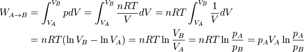
From a process from an initial state A to a final state B, with absolute temperature  constant, one finds the work required for compression (negative) or done by the expansion (positive), to be
 ,
,
where  , and so,
  . Here,
  is the absolute pressure,
 is the volume of the vessel,
  is the amount of substance of gas (mol) and
  is the ideal gas constant.
Example
How much energy can be stored in a 1 m3 storage vessel at a pressure of 70 bars (7.0 MPa), if the ambient pressure is 1 bar (0.10 MPa). In this case, the process work is
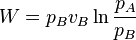 = 7.0 MPa × 1 m3 × ln(0.1 MPa/7.0 MPa) = -29.7 MJ.
The negative sign means that work is done on the gas by the surroundings. Process irreversibilities (such as in heat transfer) will result in less energy being recovered from the expansion process than is required for the compression process. If the environment is at a constant temperature, for example, the thermal resistance in the intercoolers will mean that the compression occurs at a temperature somewhat higher than the ambient temperature, and the expansion will occur at a temperature somewhat lower than ambient temperature. So a perfect isothermal storage system is impossible to achieve.
Adiabatic (isentropic) storage
An adiabatic process is one where there is no heat transfer between the fluid and the surroundings: the system is insulated against heat transfer. If the process is furthermore internally reversible (smooth, slow and frictionless, to the ideal limit) then it will additionally be isentropic.
An adiabatic storage system does away with the intercooling during the compression process, and simply allows the gas to heat up during compression, and likewise to cool down during expansion. This is attractive, since the energy losses associated with the heat transfer are avoided, but the downside is that the storage vessel must be insulated against heat loss. It should also be mentioned that real compressors and turbines are not isentropic, but instead have an isentropic efficiency of around 85%, with the result that round-trip storage efficiency for adiabatic systems is also considerably less than perfect.
Large storage system thermodynamics
Energy storage systems often use large underground caverns. This is the preferred system design, due to the very large volume, and thus the large quantity of energy that can be stored with only a small pressure change. The cavern space can be easily insulated, compressed adiabatically with little temperature change (approaching a reversible isothermal system) and heat loss (approaching an isentropic system). This advantage is in addition to the low cost of constructing the gas storage system, using the underground walls to assist in containing the pressure.
Recently there have been developed undersea insulated air bags, with similar thermodynamic properties to large underground cavern storage.[25]
Practical constraints in transportation
In order to use air storage in vehicles or aircraft for practical land or air transportation, the energy storage system must be compact and lightweight. Energy density is the engineering term that defines these desired qualities.
Energy density and efficiency
As explained in the thermodynamics of gas storage section above, compressing air heats it and expanding it cools it. Therefore practical air engines require heat exchangers in order to avoid excessively high or low temperatures and even so don't reach ideal constant temperature conditions, or ideal thermal insulation.
Nevertheless, as stated above, it is useful to describe the maximum energy storable using the isothermal case, which works out to about 100 kJ/m3 [ ln(PA/PB)].
Thus if 1.0 m3 of ambient air is very slowly compressed into a 5 L bottle at 20 MPa (200 bar), the potential energy stored is 530 kJ. A highly efficient air motor can transfer this into kinetic energy if it runs very slowly and manages to expand the air from its initial 20 MPa pressure down to 100 kPa (bottle completely "empty" at ambient pressure). Achieving high efficiency is a technical challenge both due to heat loss to the ambient and to unrecoverable internal gas heat.[26] If the bottle above is emptied to 1 MPa, the extractable energy is about 300 kJ at the motor shaft.
A standard 20 MPa, 5 L steel bottle has a mass of 7.5 kg, a superior one 5 kg. High-tensile strength fibers such as carbon-fiber or Kevlar can weigh below 2 kg in this size, consistent with the legal safety codes. One cubic meter of air at 20 °C has a mass of 1.204 kg at standard temperature and pressure.[27] Thus, theoretical energy densities are from roughly 70 kJ/kg at the motor shaft for a plain steel bottle to 180 kJ/kg for an advanced fiber-wound one, whereas practical achievable energy densities for the same containers would be from 40 to 100 kJ/kg.
Comparison with batteries
Advanced fiber-reinforced bottles are comparable to the rechargeable lead-acid battery in terms of energy density. Batteries provide nearly constant voltage over their entire charge level, whereas the pressure varies greatly while using a pressure vessel from full to empty. It is technically challenging to design air engines to maintain high efficiency and sufficient power over a wide range of pressures. Compressed air can transfer power at very high flux rates, which meets the principal acceleration and deceleration objectives of transportation systems, particularly for hybrid vehicles.
Compressed air systems have advantages over conventional batteries including longer lifetimes of pressure vessels and lower material toxicity. Newer battery designs such as those based on Lithium Iron Phosphate chemistry suffer from neither of these problems. Compressed air costs are potentially lower; however advanced pressure vessels are costly to develop and safety-test and at present are more expensive than mass-produced batteries.
As with electric storage technology, compressed air is only as "clean" as the source of the energy that it stores. Life cycle assessment addresses the question of overall emissions from a given energy storage technology combined with a given mix of generation on a power grid.
Safety
As with most technologies, compressed air has safety concerns, mainly catastrophic tank rupture. Safety codes make this a rare occurrence at the cost of higher weight and additional safety features such as pressure relief valves. Codes may limit the legal working pressure to less than 40% of the rupture pressure for steel bottles (safety factor of 2.5), and less than 20% for fiber-wound bottles (safety factor of 5). Commercial designs adopt the ISO 11439 standard.[28] High pressure bottles are fairly strong so that they generally do not rupture in vehicle crashes.
Vehicle applications
History
Air engines have been used since the 19th century to power mine locomotives, pumps, drills and trams, via centralized, city-level, distribution. Racecars use compressed air to start their internal combustion engine (ICE), and large Diesel engines may have starting pneumatic motors.

Engine
A compressed air engine uses the expansion of compressed air to drive the pistons of an engine, turn the axle, or to drive a turbine.
The following methods can increase efficiency:
- A continuous expansion turbine at high efficiency
- Multiple expansion stages
- Use of waste heat, notably in a hybrid heat engine design
- Use of environmental heat
A highly efficient arrangement uses high, medium and low pressure pistons in series, with each stage followed by an airblast venturi that draws ambient air over an air-to-air heat exchanger. This warms the exhaust of the preceding stage and admits this preheated air to the following stage. The only exhaust gas from each stage is cold air which can be as cold as −15 °C (5 °F); the cold air may be used for air conditioning in a car.[8]
Additional heat can be supplied by burning fuel as in 1904 for Whitehead's torpedoes.[29] This improves the range and speed available for a given tank volume at the cost of the additional fuel.
Cars
Since about 1990 several companies have claimed to be developing compressed air cars, but none are available. Typically the main claimed advantages are: no roadside pollution, low cost, use of cooking oil for lubrication, and integrated air conditioning.
The time required to refill a depleted tank is important for vehicle applications. "Volume transfer" moves pre-compressed air from a stationary tank to the vehicle tank almost instantaneously. Alternatively, a stationary or on-board compressor can compress air on demand, possibly requiring several hours.
Hybrid vehicles
While the air storage system offers a relatively low power density and vehicle range, its high efficiency is attractive for hybrid vehicles that use a conventional internal combustion engine as a main power source. The air storage can be used for regenerative braking and to optimize the cycle of the piston engine which is not equally efficient at all power/RPM levels.
Bosch and PSA Peugeot Citroën have developed a hybrid system that use hydraulics as a way to transfer energy to and from a compressed nitrogen tank. An up to 45% reduction in fuel consumption is claimed, corresponding to 2.9l/100 km (81 mpg, 69 g CO2/km) on the NEDC cycle for a compact frame like Peugeot 208. The system is claimed to be much more affordable than competing electric and flywheel KERS systems and is expected on road cars by 2016.[30]
Types of systems
Hybrid systems
Brayton cycle engines compress and heat air with a fuel suitable for an internal combustion engine. For example, natural gas or biogas heat compressed air, and then a conventional gas turbine engine or the rear portion of a jet engine expands it to produce work.
Compressed air engines can recharge an electric battery. The apparently defunct Energine promoted its Pne-PHEV or Pneumatic Plug-in Hybrid Electric Vehicle-system.[31]
Existing hybrid systems
Huntorf, Germany in 1978, and McIntosh, Alabama, U.S. in 1991 commissioned hybrid power plants.[9][32] Both systems use off-peak energy for air compression. The McIntosh plant achieves its 24-hour operating cycle by burning a natural gas/compressed air mix.
Future hybrid systems
The Iowa Stored Energy Park (ISEP) will use aquifer storage rather than cavern storage. The displacement of water in the aquifer results in regulation of the air pressure by the constant hydrostatic pressure of the water. A spokesperson for ISEP claims, "you can optimize your equipment for better efficiency if you have a constant pressure."[32] Power output of the McIntosh and Iowa systems is in the range of 2–300 MW.[33]
Additional facilities are under development in Norton, Ohio. FirstEnergy, an Akron, Ohio electric utility obtained development rights to the 2,700 MW Norton project in November, 2009.[34]
Lake or ocean storage
Deep water in lakes and the ocean can provide pressure without requiring high-pressure vessels or drilling into salt caverns or aquifers.[35] The air goes into inexpensive, flexible containers such as plastic bags below in deep lakes or off sea coasts with steep drop-offs. Obstacles include the limited number of suitable locations and the need for high-pressure pipelines between the surface and the containers. Since the containers would be very inexpensive, the need for great pressure (and great depth) may not be as important. A key benefit of systems built on this concept is that charge and discharge pressures are a constant function of depth. Carnot inefficiencies can thereby be reduced in the power plant. Carnot efficiency can be increased by using multiple charge and discharge stages and using inexpensive heat sources and sinks such as cold water from rivers or hot water from solar ponds. Ideally, the system must be very clever—for example, by cooling air before pumping on summer days. It must be engineered to avoid inefficiency, such as wasteful pressure changes caused by inadequate piping diameter.[36]
A nearly isobaric solution is possible if the compressed gas is used to drive a hydroelectric system. However, this solution requires large pressure tanks located on land (as well as the underwater air bags). Also, hydrogen gas is the preferred fluid, since other gases suffer from substantial hydrostatic pressures at even relatively modest depths (such as 500 meters).
E.ON, one of Europe's leading power and gas companies, has provided €1.4 million (£1.1 million) in funding to develop undersea air storage bags.[37][38] Hydrostor in Canada is developing a commercial system of underwater storage "accumulators" for compressed air energy storage, starting at the 1 to 4 MW scale.[39]
See also
- Alternative propulsion
- Compressed air battery
- Fireless locomotive
- Grid energy storage
- Hydraulic accumulator
- List of energy storage projects
- Pneumatics
- Zero-emissions vehicle
References
- ↑ Wild, Matthew, L. Wind Drives Growing Use of Batteries, New York Times, July 28, 2010, pp.B1.
- ↑ 2.0 2.1 Gies, Erica. Global Clean Energy: A Storage Solution Is in the Air, International Herald Tribune, October 1, 2012. Retrieved from NYTimes.com website, March 19, 2013.
- ↑ "ADELE – Adiabatic compressed-air energy storage (CAES) for electricity supply". Retrieved December 31, 2011.
- ↑ "German AACAES project information" (PDF). Retrieved February 22, 2008.
- ↑ "EPRI | Product Abstract". My.epri.com. Retrieved 2014-05-11.
- ↑ http://www.westgov.org/wieb/electric/Transmission%20Protocol/SSG-WI/pnw_5pp_02.pdf
- ↑ "Compressed-Air Propulsion". Aqpl43.dsl.pipex.com. Retrieved 2014-05-11.
- ↑ 8.0 8.1 "3-stage propulsion with intermediate heating". Retrieved 2014-05-11.
- ↑ 9.0 9.1 "Distributed Energy Program: Compressed Air Energy Storage". United States Department of Energy. Retrieved August 27, 2006.
- ↑ http://www.answers.com/topic/solution-mining?cat=technology ; http://www.saltinstitute.org/12.html
- ↑ 11.0 11.1 "Compressed Air Energy Storage". Pacific Northwest National Laboratory. April 2013. Retrieved May 20, 2013.
- ↑ 12.0 12.1 Chambers's Encyclopaedia: A Dictionary of Universal Knowledge. W. & R. Chambers, LTD. 1896. pp. 252–253. Retrieved January 7, 2009.
- ↑ Technische Mislukkingen, by Lex Veldhoen & Jan van den Ende, 1995/2013
- ↑ Compressed Air Storage (CAES) (PDF), Dresser-Rand Corporation, 2010, brochure form# 85230
- ↑ Wald, Matthew (September 29, 1991), Using Compressed Air To Store Up Electricity, New York Times
- ↑ CAES:McIntosh Power Plant, PowerSouth Energy Cooperative, 2010, retrieved April 15, 2012
- ↑ 17.0 17.1 ARRA Energy Storage Demonstrations (PDF), Sandia National Laboratories, retrieved April 13, 2012
- ↑ NYSEG considering Compressed Air Energy Storage, Energy Overviews Publishing, retrieved April 13, 2012
- ↑ General Compression, Inc. "What We Do – Texas Dispatachable Wind 1, LLC". Retrieved 2 March 2013.
- ↑ . Modern Power Systems http://business.highbeam.com/4364/article-1G1-297718155/adele-caes-pilot-site-selected-but-project-delayed. Missing or empty
|title=(help) - ↑ Anderson County getting energy center, retrieved July 15, 2012
- ↑ . Tyler Morning Telegraph http://www.tylerpaper.com/TP-News+Local/198477/anderson-county-power-plant-tax-bill-28m-construction-to-start-injune-on-470m-facility. Missing or empty
|title=(help) - ↑ Storelectric website
- ↑ http://www.lancashirebusinessview.co.uk/storelectric-secures-125000-angel-investment-45535/. Missing or empty
|title=(help) - ↑ Energy bags under the sea to be tested in 2011(Cleantechnica website). See in sections below.
- ↑ Heat loss of practical systems is explained in the #Thermodynamics of heat storage section.
- ↑ Air – Density and Specific Weight, The Engineering Toolbox
- ↑ "Gas cylinders – High pressure cylinders for the on-board storage of natural gas as a fuel for automotive vehicles". Iso.org. 2013-05-27. Retrieved 2014-05-11.
- ↑ "A History of the Torpedo The Early Days". Archive.is. 1999-09-18. Retrieved 2014-05-11.
- ↑ "PSA Peugeot Citroën and Bosch developing hydraulic hybrid powertrain for passenger cars; 30% reduction in fuel consumption in NEDC, up to 45% urban; B-segment application in 2016". Green Car Congress. 2013-01-22. Retrieved 2014-05-11.
- ↑ "Energine PHEV-system schematic". Energine.com. Retrieved 2014-05-11.
- ↑ 32.0 32.1 Pendick, Daniel (November 17, 2007). "Squeeze the breeze: Want to get more electricity from the wind? The key lies beneath our feet". New Scientist 195 (2623): 4. Retrieved November 17, 2007.
- ↑ Frequently Asked Questions
- ↑ "FirstEnergy Corp. Home" (PDF). Firstenergycorp.com. 2014-03-20. Retrieved 2014-05-11.
- ↑ "Wind plus compressed air equals efficient energy storage in Iowa proposal". Energy Services Bulletin website. Western Area Power Administration. Retrieved April 29, 2008.
- ↑ Prior art. Oliver Laing et al. Energy storage for off peak electricity. United States Patent No. 4873828.
- ↑ "Energy bags and super batteries". Nottingham University. June 18, 2008.
- ↑ "The man making 'wind bags'". BBC. March 26, 2008.
- ↑ "How Hydrostor Aims To Change The Power Game By Storing Energy Under Water". TechCrunch. July 9, 2011.
External links
| Wikimedia Commons has media related to Compressed air energy storage. |
- Compressed Air System of Paris – technical notes Part 1 Part 2 Part 3 Part 4 Part 5 Part 6 (Special supplement, Scientific American, 1921)
- Solution to some of country’s energy woes might be little more than hot air (Sandia National Labs, DoE).
- MSNBC article, Cities to Store Wind Power for Later Use, January 4, 2006
- Power storage: Trapped wind
- Catching The Wind In A Bottle A group of Midwest utilities is building a plant that will store excess wind power underground
- New York Times Article: Technology; Using Compressed Air To Store Up Electricity
- Compressed Air Energy Storage, Entropy and Efficiency