Capacitor voltage transformer
A capacitor voltage transformer (CVT or CCVT), is a transformer used in power systems to step down extra high voltage signals and provide a low voltage signal, for metering or operating a protective relay.
Components
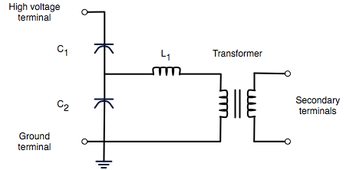
In its most basic form, the device consists of three parts: two capacitors across which the transmission line signal is split, an inductive element to tune the device to the line frequency, and a voltage transformer to isolate and further step down the voltage for the metering devices or protective relay.
The tuning of the divider to the line frequency makes the overall division ratio less sensitive to changes in the burden of the connected metering or protection devices.[1] The device has at least four terminals: a terminal for connection to the high voltage signal, a ground terminal, and two secondary terminals which connect to the instrumentation or protective relay.
In practice, capacitor C1 is often constructed as a stack of smaller capacitors connected in series. This provides a large voltage drop across C1 and a relatively small voltage drop across C2. As the majority of the voltage drop is on C1, this reduces the isolation level of the voltage transformer. This makes CVTs more economical than the wound voltage transformers under high voltage (over 100kV), as the latter one requires more winding and materials.
CVT Voltage Frequency Response
With the rated load at the voltage transformer secondary side, The output voltage of CVT initially decrease a little bit, then reaches the resonance peak at around 800 Hz. Then it decreases drastically and remains almost level out after 2000 Hz.
CVT Current Frequency Response
The C2 current is linear with frequency. The frequency response for voltage transformer current has a resonance peak at around 800 Hz. C2 current is substantially larger than voltage transformer current.
Bus Voltage Representation of CVT
The bus voltage in frequency domain can be calculated by summing the voltages on C1 and C2. From the calculation result it can be seen that the bus voltage only relates to C2 current, voltage transformer current and their ratios.This result is helpful to reconstruct the bus voltage with the C2 current, voltage transformer current. For the ratio, it can be achieved by using a summing amplifier.
Other Applications
The CVT is also useful in communication systems. CVTs in combination with wave traps are used for filtering high-frequency communication signals from power frequency.[2] This forms a carrier communication network throughout the transmission network.
See also
References
- ↑ T. Davies Protection of industrial power systems second edition, Butterworth-Heinemann, 1996 ISBN 0-7506-2662-3 page 55
- ↑ Stanley H. Horowitz, Arun G. Phadke Power system relaying third edition, John Wiley and Sons, 2008 ISBN 0-470-05712-2 pages 64–65
External links
- Brochure for a commercial CVT series (up to 1100kV) by a joint venture of General Electric and XD Group