CIECAM02

In colorimetry, CIECAM02 is the color appearance model published in 2002 by the International Commission on Illumination (CIE) Technical Committee 8-01 (Color Appearance Modelling for Color Management Systems) and the successor of CIECAM97s.[1]
The two major parts of the model are its chromatic adaptation transform, CIECAT02, and its equations for calculating mathematical correlates for the six technically defined dimensions of color appearance: brightness (luminance), lightness, colorfulness, chroma, saturation, and hue.
Brightness is the subjective appearance of how bright an object appears given its surroundings and how it is illuminated. Lightness is the subjective appearance of how light a color appears to be. Colorfulness is the degree of difference between a color and grey. Chroma is the colorfulness relative to the brightness of another color that appears white under similar viewing conditions. This allows for the fact that a surface of a given chroma displays increasing colorfulness as the level of illumination increases. Saturation is the colorfulness of a color relative to its own brightness. Hue is the degree to which a stimulus can be described as similar to or different from stimuli that are described as red, green, blue, and yellow, the so-called unique hues. The colors that make up an object’s appearance are best described in terms of lightness and chroma when talking about the colors that make up the object’s surface, and in in terms of brightness, saturation and colorfulness when talking about the light that is emitted by or reflected off the object.
CIECAM02 takes for its input the tristimulus values of the stimulus, the tristimulus values of an adapting white point, adapting background, and surround luminance information, and whether or not observers are discounting the illuminant (color constancy is in effect). The model can be used to predict these appearance attributes or, with forward and reverse implementations for distinct viewing conditions, to compute corresponding colors.
CIECAM02 is used in Windows Vista's Windows Color System.[2]
Viewing conditions
The inner circle is the stimulus, from which the tristimulus values should be measured in CIE XYZ using the 2° standard observer. The intermediate circle is the proximal field, extending out another 2°. The outer circle is the background, reaching out to 10°, from which the relative luminance (Yb) need be measured. If the proximal field is the same color as the background, the background is considered to be adjacent to the stimulus. Beyond the circles which comprise the display field (display area, viewing area) is the surround field (or peripheral area), which can be considered to be the entire room. The totality of the proximal field, background, and surround is called the adapting field (the field of view that supports adaptation—extends to the limit of vision).[3]
When referring to the literature, it is also useful to be aware of the difference between the terms adopted white point (the computational white point) and the adapted white point (the observer white point).[4] The distinction may be important in mixed mode illumination, where psychophysical phenomena come into play. This is a subject of research.
Parameter decision table
CIECAM02 defines three surround(ing)s – average, dim, and dark – with associated parameters defined here for reference in the rest of this article:[5]
| Surround condition |
Surround ratio |
F | c | Nc | Application |
|---|---|---|---|---|---|
| Average | SR > 0.2 | 1.0 | 0.69 | 1.0 | Viewing surface colors |
| Dim | 0 < SR < 0.2 | 0.9 | 0.59 | 0.95 | Viewing television |
| Dark | SR = 0 | 0.8 | 0.525 | 0.8 | Using a projector in a dark room |
- SR = Lsw / Ldw: ratio of the absolute luminance of the reference white (white point) measured in the surround field to the display area. The 0.2 coefficient derives from the "gray world" assumption (~18%–20% reflectivity). It tests whether the surround luminance is darker or brighter than medium gray.
- F: factor determining degree of adaptation
- c: impact of surrounding
- Nc: chromatic induction factor
For intermediate conditions, these values can be linearly interpolated.[5]
The absolute luminance of the adapting field, which is a quantity that will be needed later, should be measured with a photometer. If one is not available, it can be calculated using a reference white:
where Yb is the relative luminance of background, the Ew = πLW is the illuminance of the reference white in lux, LW is the absolute luminance of the reference white in cd/m2, and Yw is the relative luminance of the reference white in the adapting field. If unknown, the adapting field can be assumed to have average reflectance ("gray world" assumption): LA = LW / 5.
Note: Care should be taken not to confuse LW, the absolute luminance of the reference white in cd/m2, and Lw the red cone response in the LMS color space.
Chromatic adaptation
Summary
- Convert to the "spectrally sharpened" CAT02 LMS space to prepare for adaptation. Spectral sharpening is the transformation of the tristimulus values into new values that would have resulted from a sharper, more concentrated set of spectral sensitivities. It is argued that this aids color constancy, especially in the blue region.(Compare Finlayson et al. 94, Spectral Sharpening:Sensor Transformations for Improved Colour Constancy)
- Perform chromatic adaptation using CAT02 (also known as the "modified CMCCAT2000 transform").
- Convert to an LMS space closer to the cone fundamentals. It is argued that predicting perceptual attribute correlates is best done in such spaces.[5]
- Perform post-adaptation cone response compression.
CAT02
Given a set of tristimulus values in XYZ, the corresponding LMS values can be determined by the MCAT02 transformation matrix (calculated using the CIE 1931 2° standard colorimetric observer).[1] The sample color in the test illuminant is:
Once in LMS, the white point can be adapted to the desired degree by choosing the parameter D.[3] For the general CAT02, the corresponding color in the reference illuminant is:

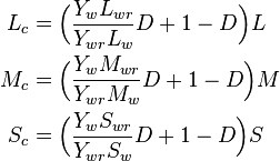
where the Yw / Ywr factor accounts for the two illuminants having the same chromaticity but different reference whites.[6] The subscripts indicate the cone response for white under the test (w) and reference illuminant (wr). The degree of adaptation (discounting) D can be set to zero for no adaptation (stimulus is considered self-luminous) and unity for complete adaptation (color constancy). In practice, it ranges from 0.65 to 1.0, as can be seen from the diagram. Intermediate values can be calculated by:[5]
where surround F is as defined above and LA is the adapting field luminance in cd/m2.[1]

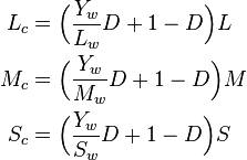
In CIECAM02, the reference illuminant has equal energy Lwr = Mwr = Swr = 100) and the reference white is the perfect reflecting diffuser (i.e., unity reflectance, and Ywr = 100) hence:
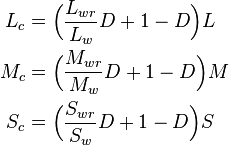
Furthermore, if the reference white in both illuminants have the Y tristimulus value (Ywr = Yw) then:
Post-adaptation
After adaptation, the cone responses are converted to the Hunt–Pointer–Estévez space by going to XYZ and back:[5]

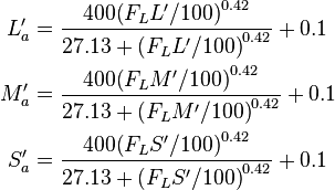
Finally, the response is compressed based on the generalized Michaelis–Menten equation (as depicted aside):[5]
FL is the luminance level adaptation factor.
As previously mentioned, if the luminance level of the background is unknown, it can estimated from the absolute luminance of the white point as LA = LW / 5 using the "medium gray" assumption. (The expression for FL is given in terms of 5LA for convenience.) In photopic conditions, the luminance level adaptation factor (FL) is proportional to the cube root of the luminance of the adapting field (LA). In scotopic conditions, it is proportional to LA (meaning no luminance level adaptation). The photopic threshold is roughly LW = 1 (see FL–LA graph above).
Appearance correlates
CIECAM02 defines correlates for yellow-blue, red-green, brightness, and colorfulness. Let us make some preliminary definitions.
The correlate for red–green (a) is the magnitude of the departure of C1 from the criterion for unique yellow (C1 = C2 / 11), and the correlate for yellow–blue (b) is based on the mean of the magnitude of the departures of C1 from unique red (C1 = C2) and unique green (C1 = C3).[3]
The 4.5 factor accounts for the fact that there are fewer cones at shorter wavelengths (the eye is less sensitive to blue). The order of the terms is such that b is positive for yellowish colors (rather than blueish).
The hue angle (h) can be found by converting the rectangular coordinate (a, b) into polar coordinates:
To calculate the eccentricity (et) and hue composition (H), determine which quadrant the hue is in with the aid of the following table. Choose i such that hi ≤ h′ < hi+1, where h′ = h if h > h1 and h′ = h + 360° otherwise.
| Red | Yellow | Green | Blue | Red | |
|---|---|---|---|---|---|
| i | 1 | 2 | 3 | 4 | 5 |
| hi | 20.14 | 90.00 | 164.25 | 237.53 | 380.14 |
| ei | 0.8 | 0.7 | 1.0 | 1.2 | 0.8 |
| Hi | 0.0 | 100.0 | 200.0 | 300.0 | 400.0 |
(This is not exactly the same as the eccentricity factor given in the table.)
Calculate the achromatic response A:
where
The correlate of lightness is
where c is the impact of surround (see above), and
The correlate of brightness is
Then calculate a temporary quantity t,
The correlate of chroma is
The correlate of colorfulness is
The correlate of saturation is
References
- ↑ 1.0 1.1 1.2 Fairchild, Mark D.; Luo, M. R.; Hunt, R. W. G. (August 2000). "A Revision of CIECAM97s for Practical Applications". Color Research & Applications (Wiley Interscience) 25 (4): 260–266. doi:10.1002/1520-6378(200008)25:4<260::AID-COL6>3.0.CO;2-9.
The CIECAM97s model was adopted by the CIE in 1997 for color imaging applications. It includes forward and reverse modes. Some problems in using this model were found in recent field trials. This article suggests revision to the model in two respects: (a) to make the lightness (J) zero when the Y tristimulus value is zero, under all surround conditions; (b) to modify the chromatic induction factor (Nc) from 1.10 to 0.95 for the dim surround condition. To avoid confusion, it is suggested that the revised version of the model be designated CAM97s2. The article also describes an alternative mode to achieve a more nearly exact reversibility between the forward and reverse modes.
- ↑ “Windows Color System: The Next Generation Color Management System”. Microsoft white paper. September 13, 2005.
- ↑ 3.0 3.1 3.2 Schanda, János (2007). "The Future of Colorimetry in the CIE: Color Appearance". Colorimetry: Understanding the CIE System. Wiley Interscience. p. 359. ISBN 978-0-470-04904-4.
- ↑ Westland, Stephen; Ripamonti, Caterina (2004). Computational Colour Science Using MATLAB. John Wiley & Sons. ISBN 0-470-84562-7.
- ↑ 5.0 5.1 5.2 5.3 5.4 5.5 Moroney, Nathan; Fairchild, Mark D.; Hunt, Robert W.G.; Li, Changjun; Luo, M. Ronnier; Newman, Todd (November 12, 2002). "The CIECAM02 Color Appearance Model". IS&T/SID Tenth Color Imaging Conference. Scottsdale, Arizona: The Society for Imaging Science and Technology. ISBN 0-89208-241-0.
- ↑ Hunt, Robert W. G.; Changjun Li; M. Ronnier Luo (February 2005). "Chromatic Adaptation Transforms". Color Research & Applications (Wiley Interscience) 30 (1): 69. doi:10.1002/col.20085.
Chromatic adaptation transforms (CATs) have appeared in different forms. The reasons for these forms, and the relationships between them, are described. The factors governing which type of CAT should be used in different applications are explained
- CIE TC 8-01 (2004). A Color appearance model for color management systems. Publication 159. Vienna: CIE Central Bureau. ISBN 3-901906-29-0.
- Fairchild, Mark D. (2004-11-09). "Color Appearance Models: CIECAM02 and Beyond". IS&T/SID 12th Color Imaging Conference. Retrieved 2008-02-11.
External links
- Excel spreadsheet with forward and inverse examples, by Eric Walowit and Grit O'Brien
- Experimental Implementation of the CIECAM02 Color Appearance Model in a Photoshop Compatible Plug-in (Windows Only), by Cliff Rames.
- Notes on the CIECAM02 Colour Appearance Model. Source code in C of the forward and reverse transforms, by Billy Biggs.
- CIECAM02 Java applet, by Nathan Moroney
| ||||||||||||||||||||||||||||||


![\begin{align}
H &= H_i + \frac{100 (h^\prime - h_i) / e_i}{(h^\prime - h_i) / e_i + (h_{i+1} - h^\prime) / e_{i+1}} \\
e_t &= \textstyle{\frac{1}{4}} \left[ \cos\left( \textstyle{\frac{\pi}{180}}h + 2\right) + 3.8 \right]
\end{align}](../I/m/d5079e797f77806d96a92abe9979e218.png)


