Bolted joint

Bolted joints are one of the most common elements in construction and machine design. They consist of fasteners that capture and join other parts, and are secured with the mating of screw threads.
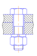
There are two main types of bolted joint designs: tension joints and shear joints.
In the tension joint, the bolt and clamped components of the joint are designed to transfer the external tension load through the joint by way of the clamped components through the design of a proper balance of joint and bolt stiffness. The joint should be designed such that the clamp load is never overcome by the external tension forces acting to separate the joint (and therefore the joined parts see no relative motion).
The second type of bolted joint transfers the applied load in shear on the bolt shank and relies on the shear strength of the bolt. Tension loads on such a joint are only incidental. A preload is still applied but is not as critical as in the case where loads are transmitted through the joint in tension. Other such shear joints do not employ a preload on the bolt as they allow rotation of the joint about the bolt, but use other methods of maintaining bolt/joint integrity. This may include clevis linkages, joints that can move, and joints that rely on a locking mechanism (like lock washers, thread adhesives, and lock nuts).
Proper joint design and bolt preload provides useful properties:
- For cyclic tension loads, the fastener is not subjected to the full amplitude of the load; as a result, the fastener's fatigue life is increased or—if the material exhibits an endurance limit its life extends indefinitely.[1]
- As long as the external tension loads on a joint do not exceed the clamp load, the fastener is not subjected to motion that would loosen it, obviating the need for locking mechanisms. (Questionable under Vibration Inputs.)
- For the shear joint, a proper clamping force on the joint components prevents relative motion of those components and the fretting wear of those that could result in the development of fatigue cracks.
In both the tension and shear joint design cases, some level of tension preload in the bolt and resulting compression preload in the clamped components is essential to the joint integrity. The preload target can be achieved by applying a measured torque to the bolt, measuring bolt extension, heating to expand the bolt then turning the nut down, torquing the bolt to the yield point, testing ultrasonically or by a certain number of degrees of relative rotation of the threaded components. Each method has a range of uncertainties associated with it, some of which are very substantial.
Theory
Typically, a bolt is tensioned (preloaded) by the application of a torque to either the bolt head or the nut. The preload developed in a bolt is due to the applied torque and is a function of the bolt diameter, length, the geometry of the threads and the coefficients of friction that exist in the threads and under the bolt head or nut. The stiffness of the components clamped by the bolt has no relation to the preload that is developed by the torque. The relative stiffness of the bolt and the clamped joint components do, however, determine the fraction of the external tension load that the bolt will carry and that in turn determines preload needed to prevent joint separation and by that means to reduce the range of stress the bolt experiences as the tension load is repeatedly applied. This determines the durability of the bolt when subjected to repeated tension loads. Maintaining a sufficient joint preload also prevents relative slippage of the joint components that would produce fretting wear that could result in a fatigue failure of those parts when subjected to in-plane shearing forces.
The clamp load, also called preload, of a fastener is created when a torque is applied, and so develops a tensile preload that is generally a substantial percentage of the fastener's proof strength. A fastener is manufactured to various standards that define, among other things, its strength and clamp load. Torque charts are available to identify the required torque for a fastener based on its property class (fineness of manufacture and fit) or grade (tensile strength).
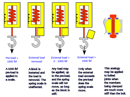
When a fastener is torqued, a tension preload develops in the bolt and a compressive preload develops in the parts being fastened. This can be modeled as a spring-like assembly that has some assumed distribution of compressive strain in the clamped joint components. When an external tension load is applied, it relieves the compressive strains induced by the preload, hence the preload acting on the compressed joint components provides the external tension load with a path other than through the bolt. As long as the forces acting on the fastened parts do not exceed the preload, the fastener's tension load will not increase.
This however, is a simplified model that is only valid when the fastened parts are much stiffer than the fastener. In reality, the fastener carries a small fraction of the external tension load even if that external load does not exceed the clamp load. When the fastened parts are less stiff than the fastener (those that use soft, compressed gaskets for example), this model breaks down and the fastener is subjected to a tension load that is the sum of the tension preload and the external tension load.
In some applications, joints are designed so that the fastener eventually fails before more expensive components. In this case, replacing an existing fastener with a higher strength fastener can result in equipment damage. Thus, it is generally good practice to replace old fasteners with new fasteners of the same grade.
Setting the torque
Engineered joints require the torque to be chosen to provide the correct preload. Applying the torque to fasteners is commonly achieved using a torque wrench.[2] The required torque value for a particular fastener application may be quoted in the published standard document, defined by the manufacturer or calculated.
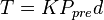
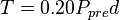
A common relationship used to calculate the torque for a desired preload takes into account the thread geometry and friction in the threads and under the bolt head or nut. The following assumes standard ISO or National Standard bolts and threads are used:
where
 is the required torque
 is the nut factor
 is the desired preload
 is the bolt diameter
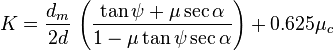
The nut factor K accounts for the thread geometry, friction, pitch. When ISO and Unified National Standard threads are used the nut factor is:[3]
where
 = the mean thread diameter, close to pitch diameter.
- = nominal bolt diameter
 = (thread pitch)/(pi * dm)
- Thread Pitch = 1/N where N is the number of threads per inch or mm
 = friction coefficient in the threads
 = half the thread angle (typically 60°) = 30°
  = friction coefficient under torqued head or nut
When a value of = =0.15 is used and the dimensions for any size bolt whether course or fine the nut factor is K ≈ 0.20 and the torque/preload relationship becomes
A study of the effect of torquing two samples, one lubricated and the other unlubricated, 1/2 in.- 20 UNF bolts to 800 lb-in, produced the same mean preload of 7700 lbf. The preloads for the unlubricated bolt sample had a standard deviation from the mean value of 1100 lbf, whereas the lubricated sample had a standard deviation of 680 lbf. If the preload value and torques are used in the above relation to solve for the nut factor it is found to be K = 0.208, which is very close to the recommended value of 0.20 [3]
| Method | Accuracy |
| Torque wrench on unlubricated bolts | ± 35% |
| Torque wrench on cad plated bolts | ± 30% |
| Torque wrench on lubricated bolts | ± 25% |
| Preload indicating washer | ± 10% |
| Strain gauges | ± 1% |
| Computer controlled wrench (below yield) | ± 15% |
| Computer controlled wrench (yield sensing) | ± 8% |
| Bolt elongation | ± 5% |
| Ultrasonic sensing | ± 5% |
The preferred bolt preload for structural applications should be at least 75% of the fastener's proof load[2] for the higher strength fasteners and as high as 90% of the proof load for permanent fasteners. To achieve the benefits of the preloading, the clamping force must be higher than the joint separation load. For some joints, multiple fasteners are required to secure the joint; these are all hand tightened before the final torque is applied to ensure an even joint seating.
The preload achieved by torquing a bolt is caused by the part of the torque that is effective. Friction in the threads and under the nut or bolt head use up some fraction of the applied torque. Much of the torque applied is lost overcoming friction under the torqued bolt head or nut (50%) and in the threads (40%). The remaining 10% of the applied torque does useful work in stretching the bolt and providing the preload. Initially, as the torque is applied, it must overcome static friction under the head of the bolt or nut (depending on which end is being torqued) and also in the threads. Finally, dynamic friction prevails and the torque is distributed in a 50/40/10 manner as the bolt is tensioned. The torque value is dependent on the friction produced in the threads and under the torqued bolt head or nut and the fastened material or washer if used. This friction can be affected by the application of a lubricant or any plating (e.g. cadmium or zinc) applied to the threads, and the fastener's standard defines whether the torque value is for dry or lubricated threading, as lubrication can reduce the torque value by 15% to 25%; lubricating a fastener designed to be torqued dry could over-tighten it, which may damage threading or stretch the fastener beyond its elastic limit, thereby reducing its clamping ability.
Either the bolt head or the nut can be torqued. If one has a larger bearing area or coefficient of friction it will require more torque to provide the same target preload.[5] Fasteners should only be torqued if they are fitted in clearance holes.
Torque wrenches do not give a direct measurement of the preload in the bolt.
More accurate methods for determining the preload rely on defining or measuring the screw extension from the nut. Alternatively, measurement of the angular rotation of the nut can serve as the basis for defining screw extension based on the fastener's thread pitch.[6] Measuring the screw extension directly allows the clamping force to be very accurately calculated. This can be achieved using a dial test indicator, reading deflection at the fastener tail, using a strain gauge, or ultrasonic length measurement.
Bolt preload can also be controlled by torquing the bolt to the point of yielding. Under some circumstances, a skilled operator can feel the drop off of the work required to turn the torque wrench as the material of the bolt begins to yield. At that point the bolt has a preload determined by the bolt area and the yield strength of the bolt material. This technique can be more accurately executed by specially built machines. Because this method only works for very high preloads and requires comparatively expensive tooling, it is only commonly used for specific applications, primarily in high performance engines.[7][8]
There is no simple method to measure the tension of a fastener already in place other than to tighten it and identify at which point the fastener starts extending. This is known as re-torqueing. An electronic torque wrench can be used on the fastener in question, so that the torque applied can be constantly measured as it is slowly increased in magnitude.
Recent developments enable tensions to be estimated by using ultrasonic testing. Another way to ensure correct tension (mainly in erecting steel) involves the use of crush-washers. These are washers that have been drilled and filled with orange RTV. When the orange rubber strands appear, the tension is correct.
Large-volume users (such as auto makers) frequently use computer controlled nut drivers. With such machines, the computer in effect plots a graph of the torque exerted. Once the torque reaches a set maximum torque chosen by the designer, the machine stops. Such machines are often used to fit wheelnuts and normally tighten all the wheel nuts simultaneously.
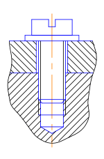
Thread engagement
Thread engagement is the length or number of threads that are engaged between the screw and the female threads. Screws are designed so that the bolt shank fails before the threads, but for this to hold true, a minimum thread engagement must be used. The following equation defines this minimum thread engagement: [9]
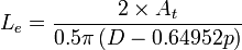
Where Le is the thread engagement length, At is the tensile stress area, D is the major diameter of the screw, and p is the pitch. This equation only holds true if the screw and female thread materials are the same. If they are not the same, then the following equations can be used to determine the additional thread length that is required:[9]
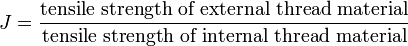

Where Le2 is the new required thread engagement.
While these formulas give absolute minimum thread engagement, many industries specify that bolted connections be at least fully engaged. For instance, the FAA has determined that in general cases, at least one thread must be protruding from any bolted connection.
Failure modes
The most common mode of failure is overloading: Operating forces of the application produce loads that exceed the clamp load, causing the joint to loosen over time or fail catastrophically.
Overtorquing might cause failure by damaging the threads and deforming the fastener, though this can happen over a very long time. Undertorquing can cause failures by allowing a joint to come loose, and it may also allow the joint to flex and thus fail under fatigue.
Brinelling may occur with poor quality washers, leading to a loss of clamp load and subsequent failure of the joint.
Other modes of failure include corrosion, embedment, and exceeding the shear stress limit.
Bolted joints may be used intentionally as sacrificial parts, which are intended to fail before other parts, as in a shear pin.
Locking mechanisms

Locking mechanisms keep bolted joints from coming loose. They are required when vibration or joint movement will cause loss of clamp load and joint failure, and in equipment where the security of bolted joints is essential.
- Jam Nuts - Two nuts, tightened on each other. In this application a thinner nut should be placed adjacent to the joint, and a thicker nut tightened onto it. The thicker nut applies more force to the joint, first relieving the force on the threads of the thinner nut and then applying a force in the opposite direction. In this way the thicker nut presses tightly on the side of the threads away from the joint, while the thinner nut presses on the side of the threads nearest the joint, tightly locking the two nuts against the threads in both directions.[10]
- Friction-locking of threads - An insert on the internal threads (either metallic or non-metallic) or a plug/patch of non-metallic material on the external threads is installed. This material binds against the threads of the opposing fastener with a friction force and creates a prevailing torque, which resists the backing-out or loosening of the fastener.[11]
- Chemical locking compounds - The use of a chemical locking compound binds the threads together when the compound cures. Examples of such a compound includes anaerobic compounds such as Loctite, which cures in the absence of oxygen and acts as an adhesive to lock the threads of the joint together.[11]
Bolt banging
Bolt banging occurs in buildings when bolted joints slip into bearing under load, thus causing a loud and potentially frightening noise resembling a rifle shot that is not, however, of structural significance and does not pose any threat to occupants. [12]
International standards
- SA-193/SA-193M: "Specification for alloy-steel and stainless steel bolting materials for high-temperature service"
- SA-194/SA-194M: "Specification for carbon and alloy steel nuts for bolts for high-temperature service"
- SA-320/SA-320M: "Specification for alloy steel bolting materials for low-temperature service"
- EN 1515: "Flanges and their joints - Bolting"
- EN 1515-1: "Flanges and their joints - Bolting - Part 1: Selection of bolting"
- EN 1515-2: "Flanges and their joints — Bolting — Part 2: Classification of bolt materials for steel flanges, PN designated"
- EN 1515-2: "Flanges and their joints — Bolting — Part 3: Classification of bolt materials for steel flanges, class designated"
- ISO 4017: "Hexagon head screws - Product grades A and B"
- ISO 4032: "Hexagon nuts, style 1 - Product grades A and B"
- ISO 4033: "Hexagon nuts, style 2 - Product grades A and B"
See also
- Bearing surface
- Bolt manufacturing process
- Castellated nut/capscrew (common in the aircraft industry)
- Quenching and tempering (Q&T)
- Rivet
- Locknut (prevailing torque nuts)
- Polymer insert nut
- Oval lock nut
- Lock washer
- Lock wire
- Mechanical joint
- Thread adhesive
- Residual stress
References
- Notes
- ↑ Collins, p. 481.
- ↑ 2.0 2.1 Oberg et al. 2004, p. 1495.
- ↑ 3.0 3.1 Shigley, Joseph (1977). Mechanical Engineering Design. McGraw-Hill. pp. 246, 247. ISBN 0-07-056881-2.
- ↑ Brown, Morrow, Durbin, Baca. "Guideline for Bolted Joint Design and Analysis: Version 1.0". Sandia Report, SAND2008-0371. Sandia National Laboratories for United States Dept. of Energy. p. 12. Retrieved 4 December 2013.
- ↑ "Bolt Science". Bolt Science Limited. Retrieved 1 December 2013.
- ↑ Oberg et al. 2004, p. 1499.
- ↑ https://www.highpowermedia.com/blog/3358/tightening-to-yield
- ↑ http://www.boltscience.com/pages/tighten.htm
- ↑ 9.0 9.1 Minimum Thread Engagement Formula and Calculation ISO, retrieved 2010-02-08.
- ↑ "The use of two nuts to prevent self loosening". boltscience.com.
- ↑ 11.0 11.1 "Vibration Loosening Of Bolts and Threaded Fasteners". boltscience.com.
- ↑ Carter, C.J.: "Steel Interchange: Banging Bolts", MSC: Modern Steel Construction, July 1999.
- Bibliography
- Collins, Jack A.; Staab, George H.; Busby, Henry R. (2002), Mechanical Design of Machine Elements and Machines, Wiley, ISBN 0-471-03307-3.
- Oberg, Erik; Jones, Franklin D.; McCauley, Christopher J.; Heald, Ricardo M. (2004), Machinery's Handbook (27th ed.), Industrial Press, ISBN 978-0-8311-2700-8.
External links
| Wikimedia Commons has media related to Bolted joints. |
- Bolt Length Calculation Method
- Bolt Formulas and Calculators
- Bolts AISC
- The banging bolt syndrome AISC
- Banging bolts — another perspective AISC
- Bolt Science - The Jost Effect
- Threaded Fasteners - Tightening to Proper Tension, US Department of Defense document MIL-HDBK-60, 2.6MB pdf.
- NASA Reference Publication 1228 Fastener Design Manual
- Mechanics of screws
- FAA Advisory Circular 43.13-1B, Paragraph 7-37 "Grip Length"
- Bolted Joint Design, Fastenal Engineering & Design Support