Attenuator (electronics)

An attenuator is an electronic device that reduces the power of a signal without appreciably distorting its waveform.
An attenuator is effectively the opposite of an amplifier, though the two work by different methods. While an amplifier provides gain, an attenuator provides loss, or gain less than 1.
Construction and usage
Attenuators are usually passive devices made from simple voltage divider networks. Switching between different resistances forms adjustable stepped attenuators and continuously adjustable ones using potentiometers. For higher frequencies precisely matched low VSWR resistance networks are used.
Fixed attenuators in circuits are used to lower voltage, dissipate power, and to improve impedance matching. In measuring signals, attenuator pads or adapters are used to lower the amplitude of the signal a known amount to enable measurements, or to protect the measuring device from signal levels that might damage it. Attenuators are also used to 'match' impedance by lowering apparent SWR.
Attenuator circuits


Basic circuits used in attenuators are pi pads (π-type) and T pads. These may be required to be balanced or unbalanced networks depending on whether the line geometry with which they are to be used is balanced or unbalanced. For instance, attenuators used with coaxial lines would be the unbalanced form while attenuators for use with twisted pair are required to be the balanced form.
Four fundamental attenuator circuit diagrams are given in the figures on the left. Since an attenuator circuit consists solely of passive resistor elements, it is linear and reciprocal. If the circuit is also made symmetrical (this is usually the case since it is usually required that the input and output impedance Z1 and Z2 are equal) then the input and output ports are not distinguished, but by convention the left and right sides of the circuits are referred to as input and output, respectively.
Attenuator characteristics

Key specifications for attenuators are:[1]
- Attenuation expressed in decibels of relative power. A 3dB pad reduces power to one half, 6dB to one fourth, 10dB to one tenth, 20dB to one hundredth, 30dB to one thousandth and so on. For voltage you double the dBs so for example 6dB is half in voltage.
- Frequency bandwidth, for example DC-18 GHz
- Power dissipation depends on mass and surface area of resistance material as well as possible additional cooling fins.
- SWR is the standing wave ratio for input and output ports
- Accuracy
- Repeatability
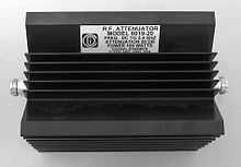
RF attenuators
Radio frequency attenuators are typically coaxial in structure with precision connectors as ports and coaxial, micro strip or thin-film internal structure. Above SHF special waveguide structure is required.
Important characteristics are:
- accuracy,
- low SWR,
- flat frequency-response and
- repeatability.
The size and shape of the attenuator depends on its ability to dissipate power. RF attenuators are used as loads for and as known attenuation and protective dissipation of power in measuring RF signals.[2]
Audio attenuators
A line-level attenuator in the preamp or a power attenuator after the power amplifier uses electrical resistance to reduce the amplitude of the signal that reaches the speaker, reducing the volume of the output. A line-level attenuator has lower power handling, such as a 1/2-watt potentiometer or voltage divider and controls preamp level signals, whereas a power attenuator has higher power handling capability, such as 10 watts or more, and is used between the power amplifier and the speaker.
Component values for resistive pads and attenuators
This section concerns pi-pads, T-pads and L-pads made entirely from resistors and terminated on each port with a purely real resistance.
- All impedance, currents, voltages and two-port parameters will be assumed to be purely real. For practical applications, this assumption is often close enough.
- The pad is designed for a particular load impedance, ZLoad, and a particular source impedance, Zs.
- The impedance seen looking into the input port will be ZS if the output port is terminated by ZLoad.
- The impedance seen looking into the output port will be ZLoad if the input port is terminated by ZS.
Reference figures for attenuator component calculation
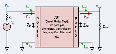


The attenuator two-port is generally bidirectional. However in this section it will be treated as though it were one way. In general, either of the two figures above applies, but the figure on the left (which depicts the source on the left) will be tacitly assumed most of the time. In the case of the L-pad, the right figure will be used if the load impedance is greater than the source impedance.
Each resistor in each type of pad discussed is given a unique designation to decrease confusion.
The L-pad component value calculation assumes that the design impedance for port 1 (on the left) is equal or higher than the design impedance for port 2.
Terms used
- Pad will include pi-pad, T-pad, L-pad, attenuator, and two-port.
- Two-port will include pi-pad, T-pad, L-pad, attenuator, and two-port.
- Input port will mean the input port of the two-port.
- Output port will mean the output port of the two-port.
- Symmetric means a case where the source and load have equal impedance.
- Loss means the ratio of power entering the input port of the pad divided by the power absorbed by the load.
- Insertion Loss means the ratio of power that would be delivered to the load if the load were directly connected to the source divided by the power absorbed by the load when connected through the pad.
Symbols used
Passive, resistive pads and attenuators are bidirectional two-ports, but in this section they will be treated as unidirectional.
- ZS = the output impedance of the source.
- ZLoad = the input impedance of the load.
- Zin = the impedance seen looking into the input port when ZLoad is connected to the output port. Zin is a function of the load impedance.
- Zout = the impedance seen looking into the output port when Zs is connected to the input port. Zout is a function of the source impedance.
- Vs = source open circuit or unloaded voltage.
- Vin = voltage applied to the input port by the source.
- Vout = voltage applied to the load by the output port.
- Iin = current entering the input port from the source.
- Iout = current entering the load from the output port.
- Pin = Vin Iin = power entering the input port from the source.
- Pout = Vout Iout = power absorbed by the load from the output port.
- Pdirect = the power that would be absorbed by the load if the load were connected directly to the source.
- Lpad = 10 log10 (Pin / Pout ) always. And if Zs = ZLoad then Lpad = 20 log10 (Vin / Vout ) also. Note, as defined, Loss ≥ 0 dB
- Linsertion = 10 log10 (Pdirect / Pout ). And if Zs = ZLoad then Linsertion = Lpad.
- Loss ≡ Lpad. Loss is defined to be Lpad.
Symmetric T pad resistor calculation
 see Valkenburg p 11-3[3]
Symmetric pi pad resistor calculation
![A = 10^{-Loss/20} \qquad R_x = R_y = Z_S \frac {1 + A} {1 - A} \qquad R_z = \frac {2R_x}{\left ( \frac {R_x}{Z_S} \right ) ^2 -1} ]\qquad \,](../I/m/738a88642535f495c6f03dfd42e18d42.png) see Valkenburg p 11-3[3]
see Valkenburg p 11-3[3]
L-Pad for impedance matching resistor calculation
If a source and load are both resistive (i.e. Z1 and Z2 have zero or very small imaginary part) then a resistive L-pad can be used to match them to each other. As shown, either side of the L-pad can be the source or load, but the Z1 side must be the side with the higher impedance.
 see Valkenburg p 11-3[4]
Large positive numbers means loss is large. The loss is a monotonic function of the impedance ratio. Higher ratios require higher loss.
Converting T-pad to pi-pad
This is the Y-Δ transform

Converting pi-pad to T-pad
This is the Δ-Y transform

Conversion between two-ports and pads
T-pad to impedance parameters
- The impedance parameters for a passive two-port are

- It is always possible to represent a resistive t-pad as a two-port. The representation is particularly simple using impedance parameters as follows:

Impedance parameters to T-pad
- The preceding equations are trivially invertible, but if the loss is not enough, some of the t-pad components will have negative resistances.

Impedance parameters to pi-pad
- These preceding T-pad parameters can be algebraically converted to pi-pad parameters.

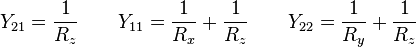
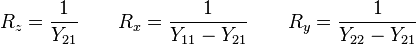
Pi-pad to admittance parameters
- The admittance parameters for a passive two port are

- It is always possible to represent a resistive pi pad as a two-port. The representation is particularly simple using admittance parameters as follows:
Admittance parameters to pi-pad
- The preceding equations are trivially invertible, but if the loss is not enough, some of the pi-pad components will have negative resistances.
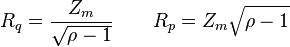
General case, determining impedance parameters from requirements
Because the pad is entirely made from resistors, it must have a certain minimum loss to match source and load if they are not equal.
The minimum loss is given by
![Loss_{min} = 20 \ log_{10} \left ( \sqrt{ \rho - 1 } + \sqrt{\rho } \quad \right ) \,
\quad \text{where} \quad \rho = \frac {\max [ Z_S, Z_{Load} ]}{\min [ Z_S, Z_{Load} ] } \,](../I/m/370d8883011beb7fa3e97b67868bb603.png)
Although a passive matching two-port can have less loss, if it does it will not be convertible to a resistive attenuator pad.

Once these parameters have been determined, they can be implemented as a T or pi pad as discussed above.
See also
Notes
- ↑ Attenuator Overview - a brief review of key specifications for fixed and step attenuators. Agilent.
- ↑ About RF attenuators - Herley General Microwave
- ↑ 3.0 3.1 3.2 Valkenburg (1998, pp. 11_3)
- ↑ Valkenburg (1998, pp. 11_3-11_5)
- ↑ 5.0 5.1 Hayt (1981, p. 494)
References
- Hayt, William; Kemmerly, Jack E. (1971), Engineering Circuit Analysis (2nd ed.), McGraw-Hill, ISBN 0-07-027382-0
- Valkenburg, Mac E. van (1998), Reference Data for Engineers: Radio, Electronics, Computer and Communication (eight ed.), Newnes, ISBN 0-7506-7064-9
External links
| Wikimedia Commons has media related to Attenuator (electronics). |