Antenna effect

The antenna effect, more formally plasma induced gate oxide damage, is an effect that can potentially cause yield and reliability problems during the manufacture of MOS integrated circuits.[1][2][3][4][5] Fabs normally supply antenna rules, which are rules that must be obeyed to avoid this problem. A violation of such rules is called an antenna violation. The word antenna is something of a misnomer in this context—the problem is really the collection of charge, not the normal meaning of antenna, which is a device for converting electromagnetic fields to/from electrical currents. Occasionally the phrase antenna effect is used in this context,[6] but this is less common since there are many effects,[7] and the phrase does not make clear which is meant.
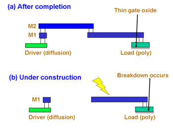
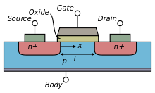
Figure 1(a) shows a side view of a typical net in an integrated circuit. Each net will include at least one driver, which must contain a source or drain diffusion (in newer technology implantation is used), and at least one receiver, which will consist of a gate electrode over a thin gate dielectric (see Figure 2 for a detailed view of a MOS transistor). Since the gate dielectric is so thin, only a few molecules thick, a big worry is breakdown of this layer. This can happen if the net somehow acquires a voltage somewhat higher than the normal operating voltage of the chip. (Historically, the gate dielectric has been silicon dioxide, so most of the literature refers to gate oxide damage or gate oxide breakdown. As of 2007, some manufacturers are replacing this oxide with various high-k dielectric materials which may or may not be oxides, but the effect is still the same.)

Once the chip is fabricated, this cannot happen, since every net has at least some source/drain implant connected to it. The source/drain implant forms a diode, which breaks down at a lower voltage than the oxide (either forward diode conduction, or reverse breakdown), and does so non-destructively. This protects the gate oxide.
However, during the construction of the chip, the oxide may not be protected by a diode. This is shown in figure 1(b), which is the situation while metal 1 is being etched. Since metal 2 is not built yet, there is no diode connected to the gate oxide. So if a charge is added in any way to the metal 1 shape (as shown by the lightning bolt) it can rise to the level of breaking down the gate oxide. In particular, reactive-ion etching of the first metal layer can result in exactly the situation shown - the metal on each net is disconnected from the initial global metal layer, and the plasma etching is still adding charges to each piece of metal.
Leaky gate oxides, although bad for power dissipation, are good for avoiding damage from the antenna effect. A leaky oxide can prevent a charge from building up to the point of causing oxide breakdown. This leads to the somewhat surprising observation that a very thin gate oxide is less likely to be damaged than a thick gate oxide, because as the oxide grows thinner, the leakage goes up exponentially, but the breakdown voltage shrinks only linearly.
Antenna rules
Antenna rules are normally expressed as an allowable ratio of metal area to gate area. There is one such ratio for each interconnect layer. The area that is counted may be more than one polygon —it is the total area of all metal connected to gates without being connected to a source/drain implant.
- If the process supports different gate oxides, such as a thick oxide for higher voltages and a thin oxide for high performance, then each oxide will have different rules.
- There are cumulative rules, where the sum (or partial sum) of the ratios over all interconnect layers sets the limit.
- There are rules that consider the periphery of each polygon, as well.
Before signing-off a physical design/layout for fabrication, the Antenna Rule Check is therefore performed.
Fixes for antenna violations

In general, antenna violations must be fixed by the router. Possible fixes include:
- Change the order of the routing layers. If the gate(s) immediately connects to the highest metal layer, no antenna violation will normally occur. This solution is shown in Figure 3(a).
- Add vias near the gate(s), to connect the gate to the highest layer used. This adds more vias, but involves fewer changes to the rest of the net. This is shown in Figure 3(b).
- Add diode(s) to the net, as shown in Figure 3(c). A diode can be formed away from a MOSFET source/drain, for example, with an n+ implant in a p-substrate or with a p+ implant in an n-well. If the diode is connected to metal near the gate(s), it can protect the gate oxide. This can be done only on nets with violations, or on every gate (in general by putting such diodes in every library cell). The "every cell" solution can fix almost all antenna problems with no need for action by any other tools. However, the extra capacitance of the diode makes the circuit slower and more power hungry.
References
- ↑ T. Watanabe, Y. Yoshida, “Dielectric Breakdown of Gate Insulator due to Reactive Etching, ” Solid State Technology, Vol. 26 (4) p. 263, Apr. 1984
- ↑ H. Shin, C. C. King, C. Hu, “Thin Oxide Damage by Plasma Etching and Ashing Processes, ” Proc. IEEE Int’l Reliability Phys. Symp., p. 37, 1992
- ↑ S. Fang, J. McVittie, “Thin-Oxide Damage from Gate Charging During Plasma Processing, ” IEEE Electron Devices Lett. Vol. 13 (5), p. 288, May 1992
- ↑ C. Gabriel, J. McVittie, “How Plasma Etching Damages Thin Gate Oxides,“ Solid State Technol. Vol. 34 (6)p. 81, June 1992.
- ↑ Hyungcheol Shin, Neeta ha, Xue-Yu Qian, Graham W. Hills, Chenming Hu, “Plasma Etching Charge-Up Damage to Thin Oxides, ’’ Solid State Technology, p. 29, Aug. 1993
- ↑ Sibille, A.; 2005, A framework for analysis of antenna effects in UWB communications, IEEE 61st Vehicular Technology Conference, Volume 1, 30 May-1 June 2005, pp. 48 - 52
- ↑ From the above reference: Several major antenna effects are considered, like impedance matching, antenna gain, frequency-dependent radiation patterns, and antenna temporal dispersion in the presence of the radio channel.