Antenna (radio)
| Part of a series on |
| Antennas |
|---|
 |
|
Common types |
|
Radiation sources / regions |
An antenna (or aerial) is an electrical device which converts electric power into radio waves, and vice versa.[1] It is usually used with a radio transmitter or radio receiver. In transmission, a radio transmitter supplies an electric current oscillating at radio frequency (i.e. a high frequency alternating current (AC)) to the antenna's terminals, and the antenna radiates the energy from the current as electromagnetic waves (radio waves). In reception, an antenna intercepts some of the power of an electromagnetic wave in order to produce a tiny voltage at its terminals, that is applied to a receiver to be amplified.
Antennas are essential components of all equipment that uses radio. They are used in systems such as radio broadcasting, broadcast television, two-way radio, communications receivers, radar, cell phones, and satellite communications, as well as other devices such as garage door openers, wireless microphones, Bluetooth-enabled devices, wireless computer networks, baby monitors, and RFID tags on merchandise.
Typically an antenna consists of an arrangement of metallic conductors (elements), electrically connected (often through a transmission line) to the receiver or transmitter. An oscillating current of electrons forced through the antenna by a transmitter will create an oscillating magnetic field around the antenna elements, while the charge of the electrons also creates an oscillating electric field along the elements. These time-varying fields radiate away from the antenna into space as a moving transverse electromagnetic field wave. Conversely, during reception, the oscillating electric and magnetic fields of an incoming radio wave exert force on the electrons in the antenna elements, causing them to move back and forth, creating oscillating currents in the antenna.
Antennas can be designed to transmit and receive radio waves in all horizontal directions equally (omnidirectional antennas), or preferentially in a particular direction (directional or high gain antennas). In the latter case, an antenna may also include additional elements or surfaces with no electrical connection to the transmitter or receiver, such as parasitic elements, parabolic reflectors or horns, which serve to direct the radio waves into a beam or other desired radiation pattern.
The first antennas were built in 1888 by German physicist Heinrich Hertz in his pioneering experiments to prove the existence of electromagnetic waves predicted by the theory of James Clerk Maxwell. Hertz placed dipole antennas at the focal point of parabolic reflectors for both transmitting and receiving. He published his work in Annalen der Physik und Chemie (vol. 36, 1889).
Terminology

The words antenna (plural: antennas[2] in US English, although both "antennas" and "antennae" are used in International English[3]) and aerial are used interchangeably. Occasionally a rigid metallic structure is called an "antenna" while the wire form is called an "aerial". However, note the important international technical journal, the IEEE Transactions on Antennas and Propagation.[4] In the United Kingdom and other areas where British English is used, the term aerial is sometimes used although 'antenna' has been universal in professional use for many years.
The origin of the word antenna relative to wireless apparatus is attributed to Italian radio pioneer Guglielmo Marconi. In the summer of 1895, Marconi began testing his wireless system outdoors on his father's estate near Bologna and soon began to experiment with long wire "aerials". Marconi discovered that by arranging these "aerials" vertically and placing them in the earth (grounding them) that the range of his wireless system was significantly increased.[5] Soon he was able to transmit signals over a hill, a distance of approximately 2.4 kilometres (1.5 mi).[6] In Italian a tent pole is known as l'antenna centrale, and the pole with the wire was simply called l'antenna. Until then wireless radiating transmitting and receiving elements were known simply as aerials or terminals.
Because of his prominence, Marconi's use of the word antenna (Italian for pole) spread among wireless researchers, and later to the general public.[7][8][9]
In common usage, the word antenna may refer broadly to an entire assembly including support structure, enclosure (if any), etc. in addition to the actual functional components. Especially at microwave frequencies, a receiving antenna may include not only the actual electrical antenna but an integrated preamplifier or mixer.
An antenna, in converting radio waves to electrical signals or vice versa, is a form of transducer.[10]
Overview
_by_night_under_the_Magellanic_Clouds.jpg)
Antennas are required by any radio receiver or transmitter to couple its electrical connection to the electromagnetic field. Radio waves are electromagnetic waves which carry signals through the air (or through space) at the speed of light with almost no transmission loss. Radio transmitters and receivers are used to convey signals (information) in systems including broadcast (audio) radio, television, mobile telephones, Wi-Fi (WLAN) data networks, trunk lines and point-to-point communications links (telephone, data networks), satellite links, many remote controlled devices such as garage door openers, and wireless remote sensors, among many others. Radio waves are also used directly for measurements in technologies including radar, GPS, and radio astronomy. In each and every case, the transmitters and receivers involved require antennas, although these are sometimes hidden (such as the antenna inside an AM radio or inside a laptop computer equipped with Wi-Fi).

According to their applications and technology available, antennas generally fall in one of two categories:
- Omnidirectional or only weakly directional antennas which receive or radiate more or less in all directions. These are employed when the relative position of the other station is unknown or arbitrary. They are also used at lower frequencies where a directional antenna would be too large, or simply to cut costs in applications where a directional antenna isn't required.
- Directional or beam antennas which are intended to preferentially radiate or receive in a particular direction or directional pattern.
In common usage "omnidirectional" usually refers to all horizontal directions, typically with reduced performance in the direction of the sky or the ground (a truly isotropic radiator is not even possible). A "directional" antenna usually is intended to maximize its coupling to the electromagnetic field in the direction of the other station, or sometimes to cover a particular sector such as a 120° horizontal fan pattern in the case of a panel antenna at a cell site.
One example of omnidirectional antennas is the very common vertical antenna or whip antenna consisting of a metal rod (often, but not always, a quarter of a wavelength long). A dipole antenna is similar but consists of two such conductors extending in opposite directions, with a total length that is often, but not always, a half of a wavelength long. Dipoles are typically oriented horizontally in which case they are weakly directional: signals are reasonably well radiated toward or received from all directions with the exception of the direction along the conductor itself; this region is called the antenna blind cone or null.

Both the vertical and dipole antennas are simple in construction and relatively inexpensive. The dipole antenna, which is the basis for most antenna designs, is a balanced component, with equal but opposite voltages and currents applied at its two terminals through a balanced transmission line (or to a coaxial transmission line through a so-called balun). The vertical antenna, on the other hand, is a monopole antenna. It is typically connected to the inner conductor of a coaxial transmission line (or a matching network); the shield of the transmission line is connected to ground. In this way, the ground (or any large conductive surface) plays the role of the second conductor of a dipole, thereby forming a complete circuit. Since monopole antennas rely on a conductive ground, a so-called grounding structure may be employed to provide a better ground contact to the earth or which itself acts as a ground plane to perform that function regardless of (or in absence of) an actual contact with the earth.
Antennas more complex than the dipole or vertical designs are usually intended to increase the directivity and consequently the gain of the antenna. This can be accomplished in many different ways leading to a plethora of antenna designs. The vast majority of designs are fed with a balanced line (unlike a monopole antenna) and are based on the dipole antenna with additional components (or elements) which increase its directionality. Antenna "gain" in this instance describes the concentration of radiated power into a particular solid angle of space, as opposed to the spherically uniform radiation of the ideal radiator. The increased power in the desired direction is at the expense of that in the undesired directions. Power is conserved, and there is no net power increase over that delivered from the power source (the transmitter.)
For instance, a phased array consists of two or more simple antennas which are connected together through an electrical network. This often involves a number of parallel dipole antennas with a certain spacing. Depending on the relative phase introduced by the network, the same combination of dipole antennas can operate as a "broadside array" (directional normal to a line connecting the elements) or as an "end-fire array" (directional along the line connecting the elements). Antenna arrays may employ any basic (omnidirectional or weakly directional) antenna type, such as dipole, loop or slot antennas. These elements are often identical.
However a log-periodic dipole array consists of a number of dipole elements of different lengths in order to obtain a somewhat directional antenna having an extremely wide bandwidth: these are frequently used for television reception in fringe areas. The dipole antennas composing it are all considered "active elements" since they are all electrically connected together (and to the transmission line). On the other hand, a superficially similar dipole array, the Yagi-Uda Antenna (or simply "Yagi"), has only one dipole element with an electrical connection; the other so-called parasitic elements interact with the electromagnetic field in order to realize a fairly directional antenna but one which is limited to a rather narrow bandwidth. The Yagi antenna has similar looking parasitic dipole elements but which act differently due to their somewhat different lengths. There may be a number of so-called "directors" in front of the active element in the direction of propagation, and usually a single (but possibly more) "reflector" on the opposite side of the active element.
Greater directionality can be obtained using beam-forming techniques such as a parabolic reflector or a horn. Since high directivity in an antenna depends on it being large compared to the wavelength, narrow beams of this type are more easily achieved at UHF and microwave frequencies.
At low frequencies (such as AM broadcast), arrays of vertical towers are used to achieve directionality [12] and they will occupy large areas of land. For reception, a long Beverage antenna can have significant directivity. For non directional portable use, a short vertical antenna or small loop antenna works well, with the main design challenge being that of impedance matching. With a vertical antenna a loading coil at the base of the antenna may be employed to cancel the reactive component of impedance; small loop antennas are tuned with parallel capacitors for this purpose.
An antenna lead-in is the transmission line (or feed line) which connects the antenna to a transmitter or receiver. The antenna feed may refer to all components connecting the antenna to the transmitter or receiver, such as an impedance matching network in addition to the transmission line. In a so-called aperture antenna, such as a horn or parabolic dish, the "feed" may also refer to a basic antenna inside the entire system (normally at the focus of the parabolic dish or at the throat of a horn) which could be considered the one active element in that antenna system. A microwave antenna may also be fed directly from a waveguide in place of a (conductive) transmission line.

An antenna counterpoise or ground plane is a structure of conductive material which improves or substitutes for the ground. It may be connected to or insulated from the natural ground. In a monopole antenna, this aids in the function of the natural ground, particularly where variations (or limitations) of the characteristics of the natural ground interfere with its proper function. Such a structure is normally connected to the return connection of an unbalanced transmission line such as the shield of a coaxial cable.
An electromagnetic wave refractor in some aperture antennas is a component which due to its shape and position functions to selectively delay or advance portions of the electromagnetic wavefront passing through it. The refractor alters the spatial characteristics of the wave on one side relative to the other side. It can, for instance, bring the wave to a focus or alter the wave front in other ways, generally in order to maximize the directivity of the antenna system. This is the radio equivalent of an optical lens.
An antenna coupling network is a passive network (generally a combination of inductive and capacitive circuit elements) used for impedance matching in between the antenna and the transmitter or receiver. This may be used to improve the standing wave ratio in order to minimize losses in the transmission line and to present the transmitter or receiver with a standard resistive impedance that it expects to see for optimum operation.
Reciprocity
It is a fundamental property of antennas that the electrical characteristics of an antenna described in the next section, such as gain, radiation pattern, impedance, bandwidth, resonant frequency and polarization, are the same whether the antenna is transmitting or receiving.[13][14] For example, the "receiving pattern" (sensitivity as a function of direction) of an antenna when used for reception is identical to the radiation pattern of the antenna when it is driven and functions as a radiator. This is a consequence of the reciprocity theorem of electromagnetics.[14] Therefore in discussions of antenna properties no distinction is usually made between receiving and transmitting terminology, and the antenna can be viewed as either transmitting or receiving, whichever is more convenient.
A necessary condition for the aforementioned reciprocity property is that the materials in the antenna and transmission medium are linear and reciprocal. Reciprocal (or bilateral) means that the material has the same response to an electric current or magnetic field in one direction, as it has to the field or current in the opposite direction. Most materials used in antennas meet these conditions, but some microwave antennas use high-tech components such as isolators and circulators, made of nonreciprocal materials such as ferrite.[13][14] These can be used to give the antenna a different behavior on receiving than it has on transmitting,[13] which can be useful in applications like radar.
Characteristics
Antennas are characterized by a number of performance measures which a user would be concerned with in selecting or designing an antenna for a particular application. Chief among these relate to the directional characteristics (as depicted in the antenna's radiation pattern) and the resulting gain. Even in omnidirectional (or weakly directional) antennas, the gain can often be increased by concentrating more of its power in the horizontal directions, sacrificing power radiated toward the sky and ground. The antenna's power gain (or simply "gain") also takes into account the antenna's efficiency, and is often the primary figure of merit.
Resonant antennas are expected to be used around a particular resonant frequency; an antenna must therefore be built or ordered to match the frequency range of the intended application. A particular antenna design will present a particular feedpoint impedance. While this may affect the choice of an antenna, an antenna's impedance can also be adapted to the desired impedance level of a system using a matching network while maintaining the other characteristics (except for a possible loss of efficiency).
Although these parameters can be measured in principle, such measurements are difficult and require very specialized equipment. Beyond tuning a transmitting antenna using an SWR meter, the typical user will depend on theoretical predictions based on the antenna design or on claims of a vendor.
An antenna transmits and receives radio waves with a particular polarization which can be reoriented by tilting the axis of the antenna in many (but not all) cases. The physical size of an antenna is often a practical issue, particularly at lower frequencies (longer wavelengths). Highly directional antennas need to be significantly larger than the wavelength. Resonant antennas usually use a linear conductor (or element), or pair of such elements, each of which is about a quarter of the wavelength in length (an odd multiple of quarter wavelengths will also be resonant). Antennas that are required to be small compared to the wavelength sacrifice efficiency and cannot be very directional. Fortunately at higher frequencies (UHF, microwaves) trading off performance to obtain a smaller physical size is usually not required.
Resonant antennas
While there are broadband designs for antennas, the vast majority of antennas are based on the half-wave dipole which has a particular resonant frequency. At its resonant frequency, the wavelength (figured by dividing the speed of light by the resonant frequency) is slightly over twice the length of the half-wave dipole (thus the name). The quarter-wave vertical antenna consists of one arm of a half-wave dipole, with the other arm replaced by a connection to ground or an equivalent ground plane (or counterpoise). A Yagi-Uda array consists of a number of resonant dipole elements, only one of which is directly connected to the transmission line. The quarter-wave elements of a dipole or vertical monopole imitate a series-resonant electrical element due to the standing wave present along the conductor. At the resonant frequency, the standing wave has a current peak and voltage node (minimum) at the feed-point, thus presenting a lower impedance than at other frequencies. What's more, the large current and small voltage are in phase at that point, resulting in a purely resistive impedance, whereas away from the design frequency the feed-point impedance both rises and becomes reactive. Contrary to an ideal (lossless) series-resonant circuit, a finite resistance remains (corresponding to the relatively small voltage at the feed-point) due to the antenna's radiation resistance (as well as any actual electrical losses).
A common misconception is that the ability of a resonant antenna to transmit (or receive) fails at frequencies far from the resonant frequency. The reason a dipole antenna needs to be used at the resonant frequency has to do with the impedance match between the antenna and the transmitter or receiver (and its transmission line). For instance, a dipole using a fairly thin conductor[15] will have a purely resistive feedpoint impedance of about 63 ohms at its design frequency. Feeding that antenna with a current of 1 ampere will require 63 volts of RF, and the antenna will radiate 63 watts (ignoring losses) of radio frequency power. If that antenna is driven with 1 ampere at a frequency 20% higher, it will still radiate as efficiently but in order to do that about 200 volts would be required due to the change in the antenna's impedance which is now largely reactive (voltage out of phase with the current). A typical transmitter would not find that impedance acceptable and would deliver much less than 63 watts to it; the transmission line would be operating at a high (poor) standing wave ratio. But using an appropriate matching network, that large reactive impedance could be converted to a resistive impedance satisfying the transmitter and accepting the available power of the transmitter.
This principle is used to construct vertical antennas substantially shorter than the 1/4 wavelength at which the antenna is resonant. By adding an inductance in series with the vertical antenna (a so-called loading coil) the capacitive reactance of this antenna can be cancelled leaving a pure resistance which can then be matched to the transmission line. Sometimes the resulting resonant frequency of such a system (antenna plus matching network) is described using the construct of "electrical length" and the use of a shorter antenna at a lower frequency than its resonant frequency is termed "electrical lengthening". For example, at 30 MHz (wavelength = 10 meters) a true resonant monopole would be almost 2.5 meters (1/4 wavelength) long, and using an antenna only 1.5 meters tall would require the addition of a loading coil. Then it may be said that the coil has "lengthened" the antenna to achieve an "electrical length" of 2.5 meters, that is, 1/4 wavelength at 30 MHz where the combined system now resonates. However, the resulting resistive impedance achieved will be quite a bit lower than the impedance of a resonant monopole, likely requiring further impedance matching. In addition to a lower radiation resistance, the reactance becomes higher as the antenna size is reduced, and the resonant circuit formed by the antenna and the tuning coil has a Q factor that rises and eventually causes the bandwidth of the antenna to be inadequate for the signal being transmitted. This is the major factor that sets the size of antennas at 1 MHz and lower frequencies.
Current and voltage distribution
The antenna conductors have the lowest feed-point impedance at the resonant frequency where they are just under 1/4 wavelength long; two such conductors in line fed differentially thus realizes the familiar "half-wave dipole". When fed with an RF current at the resonant frequency, the quarter wave element contains a standing wave with the voltage and current largely (but not exactly) in phase quadrature, as would be obtained using a quarter wave stub of transmission line. The current reaches a minimum at the end of the element (where it has nowhere to go!) and is maximum at the feed-point. The voltage, on the other hand, is the greatest at the end of the conductor and reaches a minimum (but not zero) at the feedpoint. Making the conductor shorter or longer than 1/4 wavelength means that the voltage pattern reaches its minimum somewhere beyond the feed-point, so that the feed-point has a higher voltage and thus sees a higher impedance, as we have noted. Since that voltage pattern is almost in phase quadrature with the current, the impedance seen at the feed-point is not only much higher but mainly reactive.
It can be seen that if such an element is resonant at f0 to produce such a standing wave pattern, then feeding that element with 3f0 (whose wavelength is 1/3 that of f0) will lead to a standing wave pattern in which the voltage is likewise a minimum at the feed-point (and the current at a maximum there). Thus, an antenna element is also resonant when its length is 3/4 of a wavelength (3/2 wavelength for a complete dipole). This is true for all odd multiples of 1/4 wavelength, where the feed-point impedance is purely resistive, though larger than the resistive impedance of the 1/4 wave element. Although such an antenna is resonant and works perfectly well at the higher frequency, the antenna radiation pattern is also altered compared to the half-wave dipole.
The use of a monopole or dipole at odd multiples of the fundamental resonant frequency, however, does not extend to even multiples (thus a 1/2 wavelength monopole or 1 wavelength dipole). Now the voltage standing wave is at its peak at the feed-point, while that of the current (which must be zero at the end of the conductor) is at a minimum (but not exactly zero). The antenna is anti-resonant at this frequency. Although the reactance at the feedpoint can be cancelled using such an element length, the feed-point impedance is very high, and is highly dependent on the diameter of the conductor (which makes only a small difference at the actual resonant frequency). Such an antenna does not match the much lower characteristic impedance of available transmission lines, and is generally not used. However some equipment where transmission lines are not involved which desire a high driving point impedance may take advantage of this anti-resonance.
Bandwidth
Although a resonant antenna has a purely resistive feed-point impedance at a particular frequency, many (if not most) applications require using an antenna over a range of frequencies. An antenna's bandwidth specifies the range of frequencies over which its performance does not suffer due to a poor impedance match. Also in the case of a Yagi-Uda array, the use of the antenna very far away from its design frequency reduces the antenna's directivity, thus reducing the usable bandwidth regardless of impedance matching.
Except for the latter concern, the resonant frequency of a resonant antenna can always be altered by adjusting a suitable matching network. To do this efficiently one would require remotely adjusting a matching network at the site of the antenna, since simply adjusting a matching network at the transmitter (or receiver) would leave the transmission line with a poor standing wave ratio.
Instead, it is often desired to have an antenna whose impedance does not vary so greatly over a certain bandwidth. It turns out that the amount of reactance seen at the terminals of a resonant antenna when the frequency is shifted, say, by 5%, depends very much on the diameter of the conductor used. A long thin wire used as a half-wave dipole (or quarter wave monopole) will have a reactance significantly greater than the resistive impedance it has at resonance, leading to a poor match and generally unacceptable performance. Making the element using a tube of a diameter perhaps 1/50 of its length, however, results in a reactance at this altered frequency which is not so great, and a much less serious mismatch which will only modestly damage the antenna's net performance. Thus rather thick tubes are typically used for the solid elements of such antennas, including Yagi-Uda arrays.
Rather than just using a thick tube, there are similar techniques used to the same effect such as replacing thin wire elements with cages to simulate a thicker element. This widens the bandwidth of the resonance. On the other hand, amateur radio antennas need to operate over several bands which are widely separated from each other. This can often be accomplished simply by connecting resonant elements for the different bands in parallel. Most of the transmitter's power will flow into the resonant element while the others present a high (reactive) impedance and draw little current from the same voltage. A popular solution uses so-called traps consisting of parallel resonant circuits which are strategically placed in breaks along each antenna element. When used at one particular frequency band the trap presents a very high impedance (parallel resonance) effectively truncating the element at that length, making it a proper resonant antenna. At a lower frequency the trap allows the full length of the element to be employed, albeit with a shifted resonant frequency due to the inclusion of the trap's net reactance at that lower frequency.
The bandwidth characteristics of a resonant antenna element can be characterized according to its Q, just as one uses to characterize the sharpness of an L-C resonant circuit. However it is often assumed that there is an advantage in an antenna having a high Q. After all, Q is short for "quality factor" and a low Q typically signifies excessive loss (due to unwanted resistance) in a resonant L-C circuit. However this understanding does not apply to resonant antennas where the resistance involved is the radiation resistance, a desired quantity which removes energy from the resonant element in order to radiate it (the purpose of an antenna, after all!). The Q is a measure of the ratio of reactance to resistance, so with a fixed radiation resistance (an element's radiation resistance is almost independent of its diameter) a greater reactance off-resonance corresponds to the poorer bandwidth of a very thin conductor. The Q of such a narrowband antenna can be as high as 15. On the other hand a thick element presents less reactance at an off-resonant frequency, and consequently a Q as low as 5. These two antennas will perform equivalently at the resonant frequency, but the second antenna will perform over a bandwidth 3 times as wide as the "hi-Q" antenna consisting of a thin conductor.
Gain
Gain is a parameter which measures the degree of directivity of the antenna's radiation pattern. A high-gain antenna will preferentially radiate in a particular direction. Specifically, the antenna gain, or power gain of an antenna is defined as the ratio of the intensity (power per unit surface) radiated by the antenna in the direction of its maximum output, at an arbitrary distance, divided by the intensity radiated at the same distance by a hypothetical isotropic antenna.
The gain of an antenna is a passive phenomenon - power is not added by the antenna, but simply redistributed to provide more radiated power in a certain direction than would be transmitted by an isotropic antenna. An antenna designer must take into account the application for the antenna when determining the gain. High-gain antennas have the advantage of longer range and better signal quality, but must be aimed carefully in a particular direction. Low-gain antennas have shorter range, but the orientation of the antenna is relatively inconsequential. For example, a dish antenna on a spacecraft is a high-gain device that must be pointed at the planet to be effective, whereas a typical Wi-Fi antenna in a laptop computer is low-gain, and as long as the base station is within range, the antenna can be in any orientation in space. It makes sense to improve horizontal range at the expense of reception above or below the antenna.[16]
In practice, the half-wave dipole is taken as a reference instead of the isotropic radiator. The gain is then given in dBd (decibels over dipole):
- NOTE: 0 dBd = 2.15 dBi. It is vital in expressing gain values that the reference point be included. Failure to do so can lead to confusion and error.
Effective area or aperture
The effective area or effective aperture of a receiving antenna expresses the portion of the power of a passing electromagnetic wave which it delivers to its terminals, expressed in terms of an equivalent area. For instance, if a radio wave passing a given location has a flux of 1 pW / m2 (10−12 watts per square meter) and an antenna has an effective area of 12 m2, then the antenna would deliver 12 pW of RF power to the receiver (30 microvolts rms at 75 ohms). Since the receiving antenna is not equally sensitive to signals received from all directions, the effective area is a function of the direction to the source.
Due to reciprocity (discussed above) the gain of an antenna used for transmitting must be proportional to its effective area when used for receiving. Consider an antenna with no loss, that is, one whose electrical efficiency is 100%. It can be shown that its effective area averaged over all directions must be equal to λ2/4π, the wavelength squared divided by 4π. Gain is defined such that the average gain over all directions for an antenna with 100% electrical efficiency is equal to 1. Therefore the effective area Aeff in terms of the gain G in a given direction is given by:
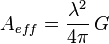
For an antenna with an efficiency of less than 100%, both the effective area and gain are reduced by that same amount. Therefore the above relationship between gain and effective area still holds. These are thus two different ways of expressing the same quantity. Aeff is especially convenient when computing the power that would be received by an antenna of a specified gain, as illustrated by the above example.
Radiation pattern

The radiation pattern of an antenna is a plot of the relative field strength of the radio waves emitted by the antenna at different angles. It is typically represented by a three-dimensional graph, or polar plots of the horizontal and vertical cross sections. The pattern of an ideal isotropic antenna, which radiates equally in all directions, would look like a sphere. Many nondirectional antennas, such as monopoles and dipoles, emit equal power in all horizontal directions, with the power dropping off at higher and lower angles; this is called an omnidirectional pattern and when plotted looks like a torus or donut.
The radiation of many antennas shows a pattern of maxima or "lobes" at various angles, separated by "nulls", angles where the radiation falls to zero. This is because the radio waves emitted by different parts of the antenna typically interfere, causing maxima at angles where the radio waves arrive at distant points in phase, and zero radiation at other angles where the radio waves arrive out of phase. In a directional antenna designed to project radio waves in a particular direction, the lobe in that direction is designed larger than the others and is called the "main lobe". The other lobes usually represent unwanted radiation and are called "sidelobes". The axis through the main lobe is called the "principal axis" or "boresight axis".
Field regions
The space surrounding an antenna can be divided into three concentric regions: the reactive near-field, the radiating near-field (Fresnell region) and the far-field (Fraunhofer) regions. These regions are useful to identify the field structure in each, although there are no precise boundaries.
In the far-field region, we are far enough from the antenna to neglect its size and shape. We can assume that the electromagnetic wave is purely a radiating plane wave (electric and magnetic fields are in phase and perpendicular to each other and to the direction of propagation). This simplifies the mathematical analysis of the radiated field.
Impedance
As an electro-magnetic wave travels through the different parts of the antenna system (radio, feed line, antenna, free space) it may encounter differences in impedance (E/H, V/I, etc.). At each interface, depending on the impedance match, some fraction of the wave's energy will reflect back to the source,[17] forming a standing wave in the feed line. The ratio of maximum power to minimum power in the wave can be measured and is called the standing wave ratio (SWR). A SWR of 1:1 is ideal. A SWR of 1.5:1 is considered to be marginally acceptable in low power applications where power loss is more critical, although an SWR as high as 6:1 may still be usable with the right equipment. Minimizing impedance differences at each interface (impedance matching) will reduce SWR and maximize power transfer through each part of the antenna system.
Complex impedance of an antenna is related to the electrical length of the antenna at the wavelength in use. The impedance of an antenna can be matched to the feed line and radio by adjusting the impedance of the feed line, using the feed line as an impedance transformer. More commonly, the impedance is adjusted at the load (see below) with an antenna tuner, a balun, a matching transformer, matching networks composed of inductors and capacitors, or matching sections such as the gamma match.
Efficiency
Efficiency of a transmitting antenna is the ratio of power actually radiated (in all directions) to the power absorbed by the antenna terminals. The power supplied to the antenna terminals which is not radiated is converted into heat. This is usually through loss resistance in the antenna's conductors, but can also be due to dielectric or magnetic core losses in antennas (or antenna systems) using such components. Such loss effectively robs power from the transmitter, requiring a stronger transmitter in order to transmit a signal of a given strength.
For instance, if a transmitter delivers 100 W into an antenna having an efficiency of 80%, then the antenna will radiate 80 W as radio waves and produce 20 W of heat. In order to radiate 100 W of power, one would need to use a transmitter capable of supplying 125 W to the antenna. Note that antenna efficiency is a separate issue from impedance matching, which may also reduce the amount of power radiated using a given transmitter. If an SWR meter reads 150 W of incident power and 50 W of reflected power, that means that 100 W have actually been absorbed by the antenna (ignoring transmission line losses). How much of that power has actually been radiated cannot be directly determined through electrical measurements at (or before) the antenna terminals, but would require (for instance) careful measurement of field strength. Fortunately the loss resistance of antenna conductors such as aluminum rods can be calculated and the efficiency of an antenna using such materials predicted.
However loss resistance will generally affect the feedpoint impedance, adding to its resistive (real) component. That resistance will consist of the sum of the radiation resistance Rr and the loss resistance Rloss. If an rms current I is delivered to the terminals of an antenna, then a power of I2Rr will be radiated and a power of I2Rloss will be lost as heat. Therefore the efficiency of an antenna is equal to Rr / (Rr + Rloss). Of course only the total resistance Rr + Rloss can be directly measured.
According to reciprocity, the efficiency of an antenna used as a receiving antenna is identical to the efficiency as defined above. The power that an antenna will deliver to a receiver (with a proper impedance match) is reduced by the same amount. In some receiving applications, the very inefficient antennas may have little impact on performance. At low frequencies, for example, atmospheric or man-made noise can mask antenna inefficiency. For example, CCIR Rep. 258-3 indicates man-made noise in a residential setting at 40 MHz is about 28 dB above the thermal noise floor. Consequently, an antenna with a 20 dB loss (due to inefficiency) would have little impact on system noise performance. The loss within the antenna will affect the intended signal and the noise/interference identically, leading to no reduction in signal to noise ratio (SNR).
This is fortunate, since antennas at lower frequencies which are not rather large (a good fraction of a wavelength in size) are inevitably inefficient (due to the small radiation resistance Rr of small antennas). Most AM broadcast radios (except for car radios) take advantage of this principle by including a small loop antenna for reception which has an extremely poor efficiency. Using such an inefficient antenna at this low frequency (530–1650 kHz) thus has little effect on the receiver's net performance, but simply requires greater amplification by the receiver's electronics. Contrast this tiny component to the massive and very tall towers used at AM broadcast stations for transmitting at the very same frequency, where every percentage point of reduced antenna efficiency entails a substantial cost.
The definition of antenna gain or power gain already includes the effect of the antenna's efficiency. Therefore if one is trying to radiate a signal toward a receiver using a transmitter of a given power, one need only compare the gain of various antennas rather than considering the efficiency as well. This is likewise true for a receiving antenna at very high (especially microwave) frequencies, where the point is to receive a signal which is strong compared to the receiver's noise temperature. However in the case of a directional antenna used for receiving signals with the intention of rejecting interference from different directions, one is no longer concerned with the antenna efficiency, as discussed above. In this case, rather than quoting the antenna gain, one would be more concerned with the directive gain which does not include the effect of antenna (in)efficiency. The directive gain of an antenna can be computed from the published gain divided by the antenna's efficiency.
Polarization
The polarization of an antenna refers to the orientation of the electric field (E-plane) of the radio wave with respect to the Earth's surface and is determined by the physical structure of the antenna and by its orientation; note that this designation is totally distinct from the antenna's directionality. Thus, a simple straight wire antenna will have one polarization when mounted vertically, and a different polarization when mounted horizontally. As a transverse wave, the magnetic field of a radio wave is at right angles to that of the electric field, but by convention, talk of an antenna's "polarization" is understood to refer to the direction of the electric field.
Reflections generally affect polarization. For radio waves, one important reflector is the ionosphere which can change the wave's polarization. Thus for signals received following reflection by the ionosphere (a skywave), a consistent polarization cannot be expected. For line-of-sight communications or ground wave propagation, horizontally or vertically polarized transmissions generally remain in about the same polarization state at the receiving location. Matching the receiving antenna's polarization to that of the transmitter can make a very substantial difference in received signal strength.
Polarization is predictable from an antenna's geometry, although in some cases it is not at all obvious (such as for the quad antenna). An antenna's linear polarization is generally along the direction (as viewed from the receiving location) of the antenna's currents when such a direction can be defined. For instance, a vertical whip antenna or Wi-Fi antenna vertically oriented will transmit and receive in the vertical polarization. Antennas with horizontal elements, such as most rooftop TV antennas in the United States, are horizontally polarized (broadcast TV in the U.S. usually uses horizontal polarization). Even when the antenna system has a vertical orientation, such as an array of horizontal dipole antennas, the polarization is in the horizontal direction corresponding to the current flow. The polarization of a commercial antenna is an essential specification.
Polarization is the sum of the E-plane orientations over time projected onto an imaginary plane perpendicular to the direction of motion of the radio wave. In the most general case, polarization is elliptical, meaning that the polarization of the radio waves varies over time. Two special cases are linear polarization (the ellipse collapses into a line) as we have discussed above, and circular polarization (in which the two axes of the ellipse are equal). In linear polarization the electric field of the radio wave oscillates back and forth along one direction; this can be affected by the mounting of the antenna but usually the desired direction is either horizontal or vertical polarization. In circular polarization, the electric field (and magnetic field) of the radio wave rotates at the radio frequency circularly around the axis of propagation. Circular or elliptically polarized radio waves are designated as right-handed or left-handed using the "thumb in the direction of the propagation" rule. Note that for circular polarization, optical researchers use the opposite right hand rule from the one used by radio engineers.
It is best for the receiving antenna to match the polarization of the transmitted wave for optimum reception. Intermediate matchings will lose some signal strength, but not as much as a complete mismatch. A circularly polarized antenna can be used to equally well match vertical or horizontal linear polarizations. Transmission from a circularly polarized antenna received by a linearly polarized antenna (or vice versa) entails a 3dB reduction in signal-to-noise ratio as the received power has thereby been cut in half.
Impedance matching
Maximum power transfer requires matching the impedance of an antenna system (as seen looking into the transmission line) to the complex conjugate of the impedance of the receiver or transmitter. In the case of a transmitter, however, the desired matching impedance might not correspond to the dynamic output impedance of the transmitter as analyzed as a source impedance but rather the design value (typically 50 ohms) required for efficient and safe operation of the transmitting circuitry. The intended impedance is normally resistive but a transmitter (and some receivers) may have additional adjustments to cancel a certain amount of reactance in order to "tweak" the match. When a transmission line is used in between the antenna and the transmitter (or receiver) one generally would like an antenna system whose impedance is resistive and near the characteristic impedance of that transmission line in order to minimize the standing wave ratio (SWR) and the increase in transmission line losses it entails, in addition to supplying a good match at the transmitter or receiver itself.
Antenna tuning generally refers to cancellation of any reactance seen at the antenna terminals, leaving only a resistive impedance which might or might not be exactly the desired impedance (that of the transmission line). Although an antenna may be designed to have a purely resistive feedpoint impedance (such as a dipole 97% of a half wavelength long) this might not be exactly true at the frequency that it is eventually used at. In some cases the physical length of the antenna can be "trimmed" to obtain a pure resistance. On the other hand, the addition of a series inductance or parallel capacitance can be used to cancel a residual capacitative or inductive reactance, respectively.
In some cases this is done in a more extreme manner, not simply to cancel a small amount of residual reactance, but to resonate an antenna whose resonance frequency is quite different from the intended frequency of operation. For instance, a "whip antenna" can be made significantly shorter than 1/4 wavelength long, for practical reasons, and then resonated using a so-called loading coil. This physically large inductor at the base of the antenna has an inductive reactance which is the opposite of the capacitative reactance that such a vertical antenna has at the desired operating frequency. The result is a pure resistance seen at feedpoint of the loading coil; unfortunately that resistance is somewhat lower than would be desired to match commercial coax.
So an additional problem beyond canceling the unwanted reactance is of matching the remaining resistive impedance to the characteristic impedance of the transmission line. In principle this can always be done with a transformer, however the turns ratio of a transformer is not adjustable. A general matching network with at least two adjustments can be made to correct both components of impedance. Matching networks using discrete inductors and capacitors will have losses associated with those components, and will have power restrictions when used for transmitting. Avoiding these difficulties, commercial antennas are generally designed with fixed matching elements or feeding strategies to get an approximate match to standard coax, such as 50 or 75 Ohms. Antennas based on the dipole (rather than vertical antennas) should include a balun in between the transmission line and antenna element, which may be integrated into any such matching network.
Another extreme case of impedance matching occurs when using a small loop antenna (usually, but not always, for receiving) at a relatively low frequency where it appears almost as a pure inductor. Resonating such an inductor with a capacitor at the frequency of operation not only cancels the reactance but greatly magnifies the very small radiation resistance of such a loop. This is implemented in most AM broadcast receivers, with a small ferrite loop antenna resonated by a capacitor which is varied along with the receiver tuning in order to maintain resonance over the AM broadcast band
Basic antenna models
There are many variations of antennas. Below are a few basic models. More can be found in Category:Radio frequency antenna types.
- The isotropic radiator is a purely theoretical antenna that radiates equally in all directions. It is considered to be a point in space with no dimensions and no mass. This antenna cannot physically exist, but is useful as a theoretical model for comparison with all other antennas. Most antennas' gains are measured with reference to an isotropic radiator, and are rated in dBi (decibels with respect to an isotropic radiator).[18]
- The dipole antenna is simply two wires pointed in opposite directions arranged either horizontally or vertically, with one end of each wire connected to the radio and the other end hanging free in space. Since this is the simplest practical antenna, it is also used as a reference model for other antennas; gain with respect to a dipole is labeled as dBd. Generally, the dipole is considered to be omnidirectional in the plane perpendicular to the axis of the antenna, but it has deep nulls in the directions of the axis.[19] Variations of the dipole include the folded dipole, the half wave antenna, the ground plane antenna, the whip, and the J-pole.
- The Yagi-Uda antenna is a directional variation of the dipole with parasitic elements added which are functionality similar to adding a reflector and lenses (directors) to focus a filament light bulb.[20]
- The random wire antenna is simply a very long (at least one quarter wavelength) wire with one end connected to the radio and the other in free space, arranged in any way most convenient for the space available. Folding will reduce effectiveness and make theoretical analysis extremely difficult. (The added length helps more than the folding typically hurts.) Typically, a random wire antenna will also require an antenna tuner, as it might have a random impedance that varies non-linearly with frequency.[21]
- The horn antenna is used where high gain is needed, the wavelength is short (microwave) and space is not an issue. Horns can be narrow band or wide band, depending on their shape. A horn can be built for any frequency, but horns for lower frequencies are typically impractical. Horns are also frequently used as reference antennas.[22]
- The parabolic antenna consists of an active element at the focus of a parabolic reflector to reflect the waves into a plane wave. Like the horn it is used for high gain, microwave applications, such as satellite dishes.[23]
- The patch antenna consists mainly of a square conductor mounted over a groundplane. Another example of a planar antenna is the tapered slot antenna (TSA), as the Vivaldi-antenna.
Examples of antenna models
-

Dipole antenna ("Rabbit ears") for television reception
-

Folded dipole antenna
-

A Yagi-Uda beam antenna
-

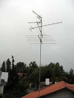
Rooftop TV antenna. It is actually three Yagi antennas. The longest elements are for the low band, while the medium and short elements are for the high and UHF band.
-

A random wire antenna
-

Pyramidal microwave horn antenna
-

Large parabolic antenna for communicating with spacecraft
-

A patch antenna and a cutaway view
Antenna design criteria

Almost any arrangement of conductors with radio frequency currents driven by a voltage applied across two points will radiate as an antenna. However to be practical an antenna will be designed to meet certain specifications among the characteristics listed above. One extremely important characteristic is the driving point impedance, as this impedance is usually very large (and highly reactive) for an arbitrarily designed antenna, or even for a well designed antenna used at a frequency well outside of its design range. For non-directional antennas, forcing the impedance to a usable value (often that of the transmission line to be used to connect to it) and an impedance with a relatively small amount of reactance, is the main design task. For instance, the design of dipole antennas (which many other antennas are based on) dictates a total length just under half the wavelength (thus each arm being one quarter wavelength). This provides a purely resistive feedpoint impedance (at the design frequency) of a bit under 72Ω (depending on the diameter of the conductors). Likewise, a dipole antenna which is an odd multiple of half wavelengths long will supply a reasonable (but different) feedpoint impedance which is purely resistive. Such an antenna used at the frequency where its driving point impedance is purely resistive is called a resonant antenna, even though the "resonance" involved usually is characterized by a rather low Q. In fact a small Q factor is generally sought, since a larger Q implies a smaller bandwidth over which the antenna will provide a good impedance match to the transmission line or matching network. In the case of a dipole antenna, increasing the diameter of the two conductors, increases the usable bandwidth of the antenna.
Having thus eliminated reactance from the feedpoint impedance, what remains is a pure resistance, which is the sum of two parts. The main part (usually) is the radiation resistance due to the conversion of electrical energy into a transmitted wave. Of course this is what the antenna was meant to do. But there can be an additional contribution to the feedpoint impedance due to the ohmic resistance of the conductors, which is a source of inefficiency. This inefficiency can be reduced by using larger conductors, for instance, but that will have other effects as well.
The third important design criterion for many antennas is the antenna's directionality (expressed by its radiation pattern and gain). This is often not a design goal however. An antenna much smaller than a wavelength in all its dimensions cannot have much directionality, so at lower frequencies a directional antenna generally becomes impractically large. Antennas for use in portable or mobile equipment cannot be conveniently pointed in the direction of the other station, so directionality is undesired in these applications. The vertical "whip" antenna, for instance, is completely omnidirectional in the horizontal plane, and widely used in such applications.
However for fixed stations communicating with other fixed stations, directionality allows for a significant antenna gain (factor by which power is concentrated in one direction), improving the received signal level by that factor. Thus a beam antenna with a 13dB gain compared to an omnidirectional antenna, will allow use of a transmitter of only 1/20th of the power. A rural location might require a Yagi rooftop antenna with such a gain for TV reception, whereas increasing the TV station's power by a factor of 20 would be out of the question. At higher and higher frequencies, the feasibility of higher gain (more directional) antennas increases, with high gain microwave antennas typically employing parabolic reflectors or horns.
The gain of such a directional antenna will also have a certain operating bandwidth, in addition to the bandwidth associated with the feedpoint impedance. Thus the Yagi TV antenna will only maintain its high gain over a few TV channels. For use over an entire frequency band, a wideband design such as the log periodic antenna may be chosen. Although superficially similar in appearance to a high gain Yagi, the log-periodic dipole array often used for TV can cover the entire UHF TV band, for instance. In return for being wideband, however, the antenna gain is much less than that of a comparable Yagi. Practical antenna designs always involve such trade-offs in order to best meet the performance requirements imposed by a particular application.
Effect of ground
Ground reflections is one of the common types of multipath.[24][25][26]
The radiation pattern and even the driving point impedance of an antenna can be influenced by the dielectric constant and especially conductivity of nearby objects. For a terrestrial antenna, the ground is usually one such object of importance. The antenna's height above the ground, as well as the electrical properties (permittivity and conductivity) of the ground, can then be important. Also, in the particular case of a monopole antenna, the ground (or an artificial ground plane) serves as the return connection for the antenna current thus having an additional effect, particularly on the impedance seen by the feed line.
When an electromagnetic wave strikes a plane surface such as the ground, part of the wave is transmitted into the ground and part of it is reflected, according to the Fresnel coefficients. If the ground is a very good conductor then almost all of the wave is reflected (180° out of phase), whereas a ground modeled as a (lossy) dielectric can absorb a large amount of the wave's power. The power remaining in the reflected wave, and the phase shift upon reflection, strongly depend on the wave's angle of incidence and polarization. The dielectric constant and conductivity (or simply the complex dielectric constant) is dependent on the soil type and is a function of frequency.
For very low frequencies to high frequencies (<30 MHz), the ground behaves as a lossy dielectric, [27] Thus the ground is characterized both by a conductivity [28] and permittivity (dielectric constant) which can be measured for a given soil (but is influenced by fluctuating moisture levels) or can be estimated from certain maps. At lower frequencies the ground acts mainly as a good conductor, which AM middle wave broadcast (.5 - 1.6 MHz) antennas depend on.
At frequencies between 3 and 30 MHz, a large portion of the energy from a horizontally polarized antenna reflects off the ground, with almost total reflection at the grazing angles important for ground wave propagation. That reflected wave, with its phase reversed, can either cancel or reinforce the direct wave, depending on the antenna height in wavelengths and elevation angle (for a sky wave).
On the other hand, vertically polarized radiation is not well reflected by the ground except at grazing incidence or over very highly conducting surfaces such as sea water. [29] However the grazing angle reflection important for ground wave propagation, using vertical polarization, is in phase with the direct wave, providing a boost of up to 6 db, as is detailed below.

At VHF and above (>30MHz) the ground becomes a poorer reflector. However it remains a good reflector especially for horizontal polarization and grazing angles of incidence. That is important as these higher frequencies usually depend on horizontal line-of-sight propagation (except for satellite communications), the ground then behaving almost as a mirror.
The net quality of a ground reflection depends on the topography of the surface. When the irregularities of the surface are much smaller than the wavelength, we are in the regime of specular reflection, and the receiver sees both the real antenna and an image of the antenna under the ground due to reflection. But if the ground has irregularities not small compared to the wavelength, reflections will not be coherent but shifted by random phases. With shorter wavelengths (higher frequencies), this is generally the case.
Whenever both the receiving or transmitting antenna are placed at significant heights above the ground (relative to the wavelength), waves specularly reflected by the ground will travel a longer distance than direct waves, inducing a phase shift which can sometimes be significant. When a sky wave is launched by such an antenna, that phase shift is always significant unless the antenna is very close to the ground (compared to the wavelength).
The phase of reflection of electromagnetic waves depends on the polarization of the incident wave. Given the larger refractive index of the ground (typically n=2) compared to air (n=1), the phase of horizontally polarized radiation is reversed upon reflection (a phase shift of  radians or 180°). On the other hand, the vertical component of the wave's electric field is reflected at grazing angles of incidence approximately in phase. These phase shifts apply as well to a ground modelled as a good electrical conductor.

This means that a receiving antenna "sees" an image of the antenna but with reversed currents. That current is in the same absolute direction as the actual antenna if the antenna is vertically oriented (and thus vertically polarized) but opposite the actual antenna if the antenna current is horizontal.
The actual antenna which is transmitting the original wave then also may receive a strong signal from its own image from the ground. This will induce an additional current in the antenna element, changing the current at the feedpoint for a given feedpoint voltage. Thus the antenna's impedance, given by the ratio of feedpoint voltage to current, is altered due to the antenna's proximity to the ground. This can be quite a significant effect when the antenna is within a wavelength or two of the ground. But as the antenna height is increased, the reduced power of the reflected wave (due to the inverse square law) allows the antenna to approach its asymptotic feedpoint impedance given by theory. At lower heights, the effect on the antenna's impedance is very sensitive to the exact distance from the ground, as this affects the phase of the reflected wave relative to the currents in the antenna. Changing the antenna's height by a quarter wavelength, then changes the phase of the reflection by 180°, with a completely different effect on the antenna's impedance.
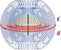
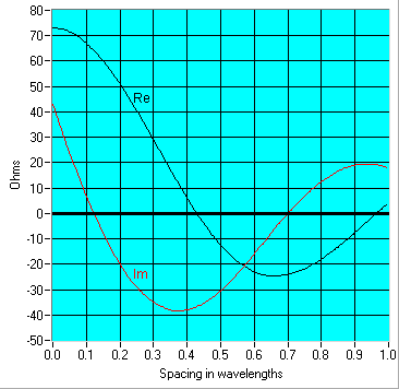
The ground reflection has an important effect on the net far field radiation pattern in the vertical plane, that is, as a function of elevation angle, which is thus different between a vertically and horizontally polarized antenna. Consider an antenna at a height h above the ground, transmitting a wave considered at the elevation angle θ. For a vertically polarized transmission the magnitude of the electric field of the electromagnetic wave produced by the direct ray plus the reflected ray is:

Thus the power received can be as high as 4 times that due to the direct wave alone (such as when θ=0), following the square of the cosine. The sign inversion for the reflection of horizontally polarized emission instead results in:

where:
-
 is the electrical field that would be received by the direct wave if there were no ground.
 - θ is the elevation angle of the wave being considered.
-
 is the wavelength.
 -
 is the height of the antenna (half the distance between the antenna and its image).

For horizontal propagation between transmitting and receiving antennas situated near the ground reasonably far from each other, the distances traveled by tne direct and reflected rays are nearly the same. There is almost no relative phase shift. If the emission is polarized vertically, the two fields (direct and reflected) add and there is maximum of received signal. If the signal is polarized horizontally, the two signals subtract and the received signal is largely cancelled. The vertical plane radiation patterns are shown in the image at right. With vertical polarization there is always a maximum for θ=0, horizontal propagation (left pattern). For horizontal polarization, there is cancellation at that angle. Note that the above formulae and these plots assume the ground as a perfect conductor. These plots of the radiation pattern correspond to a distance between the antenna and its image of 2.5λ. As the antenna height is increased, the number of lobes increases as well.
The difference in the above factors for the case of θ=0 is the reason that most broadcasting (transmissions intended for the public) uses vertical polarization. For receivers near the ground, horizontally polarized transmissions suffer cancellation. For best reception the receiving antennas for these signals are likewise vertically polarized. In some applications where the receiving antenna must work in any position, as in mobile phones, the base station antennas use mixed polarization, such as linear polarization at an angle (with both vertical and horizontal components) or circular polarization.
On the other hand, classical (analog) television transmissions are usually horizontally polarized, because in urban areas buildings can reflect the electromagnetic waves and create ghost images due to multipath propagation. Using horizontal polarization, ghosting is reduced because the amount of reflection of electromagnetic waves in the p polarization (horizontal polarization off the side of a building) is generally less than s (vertical, in this case) polarization. Vertically polarized analog television has nevertheless been used in some rural areas. In digital terrestrial television such reflections are less problematic, due to robustness of binary transmissions and error correction.
Mutual impedance and interaction between antennas
Current circulating in one antenna generally induces a voltage across the feedpoint of nearby antennas or antenna elements. The mathematics presented below are useful in analyzing the electrical behaviour of antenna arrays, where the properties of the individual array elements (such as half wave dipoles) are already known. If those elements were widely separated and driven in a certain amplitude and phase, then each would act independently as that element is known to. However because of the mutual interaction between their electric and magnetic fields due to proximity, the currents in each element are not simply a function of the applied voltage (according to its driving point impedance), but depend on the currents in the other nearby elements. Note that this now is a near field phenomenon which could not be properly accounted for using the Friis transmission equation for instance.
The elements' feedpoint currents and voltages can be related to each other using the concept of mutual impedance  between every pair of antennas just as the mutual impedance
  describes the voltage induced in one inductor by a current through a nearby coil coupled to it through a mutual inductance M. The mutual impedance
  between two antennas is defined[30] as:

where  is the current flowing in antenna i and
  is the voltage induced at the open-circuited feedpoint of antenna j due to
  when all other currents ik are zero. The mutual impendances can be viewed as the elements of a symmetric square impedance matrix Z. Note that the diagonal elements,
  , are simply the driving point impedances of each element.
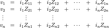
Using this definition, the voltages present at the feedpoints of a set of coupled antennas can be expressed as the multiplication of the impedance matrix times the vector of currents. Written out as discrete equations, that means:
where:
-
 is the voltage at the terminals of antenna
-
 is the current flowing between the terminals of antenna
 -
 is the driving point impedance of antenna
 -
 is the mutual impedance between antennas and
  .
.
As is the case for mutual inductances,

This is a consequence of Lorentz reciprocity. For an antenna element not connected to anything (open circuited) one can write  . But for an element which is short circuited, a current is generated across that short but no voltage is allowed, so the corresponding
  . This is the case, for instance, with the so-called parasitic elements of a Yagi-Uda antenna where the solid rod can be viewed as a dipole antenna shorted across its feedpoint. Parasitic elements are unpowered elements that absorb and reradiate RF energy according to the induced current calculated using such a system of equations.
With a particular geometry, it is possible for the mutual impedance between nearby antennas to be zero. This is the case, for instance, between the crossed dipoles used in the turnstile antenna.
Antenna gallery
Antennas and antenna arrays
-

A multi-band rotary directional antenna for amateur radio use.
-
A terrestrial microwave radio antenna array.
-

Wire dipole antenna using open-wire ladder line feedline for amateur radio use.
-

Low cost LF time signal receiver, antenna (left) and receiver
-

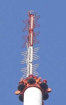
Rotatable log-periodic array for VHF and UHF.
-

Shortwave antennas in Delano, California.
-

AM loop antenna
Antennas and supporting structures
-

A water tower in Palmerston, Northern Territory with radio broadcasting and communications antennas.
-
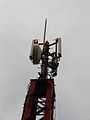
A three-sector telephone site in Mexico City.
-
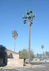
Telephone site concealed as a palm tree.

Diagrams as part of a system
-
Antennas may be connected through a multiplexing arrangement in some applications like this trunked two-way radio example.
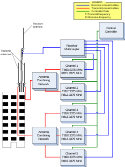
-

Antenna network for an emergency medical services base station.
See also
| Wikimedia Commons has media related to Antennas. |
- Amateur radio
- Antenna measurement
- AWX antenna
- Category:Radio frequency antenna types
- Category:Radio frequency propagation
- Cellular repeater
- DXing
- Electromagnetism
- Fractal antenna
- Mast radiator
- Mobile broadband modem
- Numerical Electromagnetics Code
- Radio masts and towers
- Radio telescope
- RF connector
- Satellite television
- Smart antenna
- Television antenna
- TETRA
- Whip antenna
Notes
- ↑ Graf, Rudolf F. (1999). Modern Dictionary of Electronics. Newnes. p. 29. ISBN 0750698667.
- ↑ In the context of electrical engineering and physics, the plural of antenna is antennas, and it has been this way since about 1950 (or earlier), when a cornerstone textbook in this field, Antennas, was published by the physicist and electrical engineer John D. Kraus of The Ohio State University. Besides in the title, Dr. Kraus noted this in a footnote on the first page of his book. Insects may have "antennae", but this form is not used in the context of electronics or physics.
- ↑ For example http://www.telegraph.co.uk/science/science-news/7810454/British-scientists-launch-major-radio-telescope.html; http://www.ic.gc.ca/eic/site/smt-gst.nsf/eng/sf09377.html; http://www.ska.ac.za/media/meerkat_cad.php
- ↑ "IEEE Transactions on Antennas and Propagation".
- ↑ Marconi, "Wireless Telegraphic Communication: Nobel Lecture, 11 December 1909." Nobel Lectures. Physics 1901–1921. Amsterdam: Elsevier Publishing Company, 1967: 196–222. p. 206.
- ↑ "The Nobel Prize in Physics 1909".
- ↑ Slyusar, Vadym (20–23 September 2011). "To history of radio engineering’s term "antenna"" (PDF). VIII International Conference on Antenna Theory and Techniques (ICATT’11). Kyiv, Ukraine. pp. 83–85.
- ↑ Slyusar, Vadym (21–24 February 2012). "An Italian period on the history of radio engineering’s term "antenna"" (PDF). 11th International Conference Modern Problems of Radio Engineering, Telecommunications and Computer Science (TCSET’2012). Lviv-Slavske, Ukraine. p. 174.
- ↑ Slyusar, Vadym (June 2011). "Антенна: история радиотехнического термина" [The Antenna: A History of Radio Engineering’s Term] (PDF). ПЕРВАЯ МИЛЯ Last mile: Electronics: Science, Technology, Business (in Russian) ? (6): 52–64.
- ↑ Schantz, Hans Gregory (2003), "Introduction to ultra-wideband antennas" (PDF), Proceedings of the 2003 IEEE UWBST Conference.
- ↑ "Media Advisory: Apply Now to Attend the ALMA Observatory Inauguration". ESO Announcement. Retrieved 4 December 2012.
- ↑ Carl Smith (1969). Standard Broadcast Antenna Systems, p. 2-1212. Cleveland, Ohio: Smith Electronics, Inc.
- ↑ 13.0 13.1 13.2 Lonngren, Karl Erik; Savov, Sava V.; Jost, Randy J. (2007). Fundamentals of Electomagnetics With Matlab, 2nd Ed. SciTech Publishing. p. 451. ISBN 1891121588.
- ↑ 14.0 14.1 14.2 Stutzman, Warren L.; Thiele, Gary A. (2012). Antenna Theory and Design, 3rd Ed. John Wiley & Sons. pp. 560–564. ISBN 0470576642.
- ↑ This example assumes a length to diameter ratio of 1000.
- ↑ "Guide to Wi-Fi Wireless Network Antenna Selection.". NetworkBits.net. Archived from the original on 5 March 2008. Retrieved April 8, 2008.
- ↑ Impedance is caused by the same physics as refractive index in optics, although impedance effects are typically one-dimensional, where effects of refractive index is three-dimensional.
- ↑ Krauss, John D. (1950). Antennas. New York: McGraw Hill. pp. 15,53–54.
- ↑ Krauss 1950, pp. 127-148
- ↑ Krauss 1950, pp. 318-321
- ↑ Krauss 1950, p. 407
- ↑ Krauss 1950, pp. 371-381
- ↑ Krauss 1950, pp. 336-348
- ↑ Fixed Broadband Wireless System Design, p. 130, at Google Books
- ↑ Monopole Antennas, p. 340, at Google Books
- ↑ Wireless and Mobile Communication, p. 37, at Google Books
- ↑ H. Ward Silver, ed. (2011). ARRL Antenna Book, p. 3-2. Newington, Connecticut: American Radio Relay League. ISBN 978-0-87259-694-8
- ↑ http://www.fcc.gov/encyclopedia/m3-map-effective-ground-conductivity-united-states-wall-sized-map-am-broadcast-stations
- ↑ H. Ward Silver, ed. (2011). ARRL Antenna Book, p. 3-23. Newington, Connecticut: American Radio Relay League. ISBN 978-0-87259-694-8
- ↑ Kai Fong Lee (1984). Principles of Antenna Theory. John Wiley and Sons Ltd. ISBN 0-471-90167-9.
References
General references
- Antenna Theory (3rd edition), by C. Balanis, Wiley, 2005, ISBN 0-471-66782-X;
- Antenna Theory and Design (2nd edition), by W. Stutzman and G. Thiele, Wiley, 1997, ISBN 0-471-02590-9;
- Antennas (4th edition), by J. Kraus and R. Marhefka, McGraw-Hill, 2001, ISBN 0-07-232103-2;
- Antennenbuch, by Karl Rothammel, publ. Franck'sche Verlagshandlung Stuttgart, 1991, ISBN 3-440-05853-0; other editions (in German)
- Antennas for portable Devices, Zhi Ning Chen (edited), John Wiley & Sons in March 2007
- Broadband Planar Antennas: Design and Applications, Zhi Ning Chen and M. Y. W. Chia, John Wiley & Sons in February 2006
- The ARRL Antenna Book (15th edition), ARRL, 1988, ISBN 0-87259-206-5
"Practical antenna" references
- Antenna Theory antenna-theory.com
- Antennas Antenna types
- Patch Antenna: From Simulation to Realization EM Talk
- Why Antennas Radiate, Stuart G. Downs, WY6EE (PDF)
- Understanding electromagnetic fields and antenna radiation takes (almost) no math, Ron Schmitt, EDN Magazine, March 2 2000 (PDF)
- Antennas: Generalities, Principle of operation, As electronic component, Hertz Marconi and Other types Antennas etc etc
Theory and simulations
- AN-SOF, "Antenna Simulation Software". Program system for the modeling of antennas and scatterers.
- http://www.dipoleanimator.com
- EM Talk, "Microstrip Patch Antenna", (Theory and simulation of microstrip patch antenna)
- "Online Calculations and Conversions " Formulas for simulating and optimizing Antenna specs and placement
- "Microwave Antenna Design Calculator" Provides quick estimation of antenna size required for a given gain and frequency. 3 dB and 10 dB beamwidths are also derived; the calculator additionally gives the far-field range required for a given antenna.
- Sophocles J. Orfanidis, "Electromagnetic Waves and Antennas", Rutgers University (20 PDF Chaps. Basic theory, definitions and reference)
- Hans Lohninger, "Learning by Simulations: Physics: Coupled Radiators". vias.org, 2005. (ed. Interactive simulation of two coupled antennas)
- NEC Lab - NEC Lab is a tool that uses Numerical Electromagnetics Code and Artificial Intelligence to design and simulate antennas.
- Justin Smith "Aerials". A.T.V (Aerials and Television), 2009. (ed. Article on the (basic) theory and use of FM, DAB & TV aerials)
- Antennas Research Group, "Virtual (Reality) Antennas". Democritus University of Thrace, 2005.
- "Support > Knowledgebase > RF Basics > Antennas / Cables > dBi vs. dBd detail". MaxStream, Inc., 2005. (ed. How to measure antenna gain) (New location: http://www.digi.com/support/kbase/kbaseresultdetl?id=2146 Note: to skip the registration form click the link below it)
- Yagis and Log Periodics, Astrosurf article.
- Raines, J. K., "Virtual Outer Conductor for Linear Antennas," Microwave Journal, Vol. 52, No. 1, January, 2009, pp. 76–86
- Tests of FM/VHF receiving antennas.
- Effect of ground references
- Electronic Radio and Engineering. F.E. Terman. McGraw-Hill
- Lectures on physics. Feynman, Leighton and Sands. Addison-Wesley
- Classical Electricity and Magnetism. W. Panofsky and M. Phillips. Addison-Wesley
Patents and USPTO
- CLASS 343, Communication: Radio Wave Antenna
Further reading
- Antennas for Base Stations in Wireless Communications, edited by Zhi Ning Chen and Kwai-Man Luk, McGraw-Hill Companies, Inc, USA in May 2009
![]() The dictionary definition of antenna at Wiktionary
The dictionary definition of antenna at Wiktionary
| ||||||||||||||||||||||||||||||||||||||||||
| ||||||||||||||||||||||||||||||||||||||||||||||||||||||||||||||||||||||||||||||||||||||||||||||||||||||||||||||||||