Wire-frame model


A wire frame model is a visual presentation of a three dimensional or physical object used in 3D computer graphics. It's created by specifying each edge of the physical object where two mathematically continuous smooth surfaces meet, or by connecting an object's constituent vertices using straight lines or curves. The object is projected onto the computer screen by drawing lines at the location of each edge. The term wireframe comes from designers using metal wire to represent the 3 dimensional shape of solid objects. 3D wireframe allows to construct and manipulate solids and solid surfaces. The 3D solid modeling technique efficiently draws higher quality representations of solids than the conventional line drawing.
Using a wire frame model allows visualization of the underlying design structure of a 3D model. Traditional 2-dimensional views and drawings can be created by appropriate rotation of the object and selection of hidden line removal via cutting planes.
Since wireframe renderings are relatively simple and fast to calculate, they are often used in cases where a high screen frame rate is needed (for instance, when working with a particularly complex 3D model, or in real-time systems that model exterior phenomena). When greater graphical detail is desired, surface textures can be added automatically after completion of the initial rendering of the wireframe. This allows the designer to quickly review chansolids or rotate the object to new desired views without long delays associated with more realistic rendering.
The wire frame format is also well suited and widely used in programming tool paths for DNC (Direct Numerical Control) machine tools.
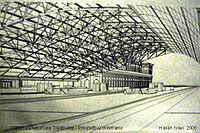
Hand-drawn wireframe-like illustrations date back as far as the Italian Renaissance.[1] Wireframe models were also used extensively in video games to represent 3D objects during the 1980s and early 1990s when properly filled 3D objects would have been too complex to calculate and draw with the computers of the time. Wireframe models are also used as the input for CAM(computer-aided manufacturing).
There are mainly three types of 3D CAD models. Wireframe is one of them and it is most abstract and least realistic. Other types of 3D CAD models are surface and solid. This method of modelling consists only lines, points and curves defining the edges of an object.
Introduction
Wireframing is one of the method of geometric modelling system. A wireframe model represents shape of solid object by its characteristics lines and points. There are two types of wireframe modelling.1)Pro's and 2)Con's. In Pro's user gives a simple input to create a shape. It is useful in developing system. While in Con's wireframe model, it does not include information about inside and outside boundary surfaces.Now-a-days in mechanical design wireframe models are used in defining complex solid objects. The designer makes wireframe model of a solid object first and then CAD operator reconstructs the object including detailed analysis. In this way a solid object is created indirectly by using wireframe technique. This technique has some advantage as follow-1)Generally the 3 dimensional solid objects are complex, wireframe model can be viewed in 1 dimension so this compactness helps designer.2)The solid object can be modified further. The designer can ignore the geometry inside surface while in solid modelling designer has to give consistent geometry for all details.3)Wireframe models require less space and also very few resources from CPU.
Simple example of wireframe model
An object is specified by two tables: the vertex table and the edge table. The vertex table consists of three-dimensional coordinate values for each vertex with reference to the origin, while the edge table specifies the start and end vertices for each edge. After the appropriate calculations have been performed to transform the 3D coordinates of the vertices into 2D screen coordinates, a naïve interpretation could create a wireframe representation by simply drawing straight lines between the screen coordinates of the appropriate vertices using the edge list. Unlike representations designed for more detailed rendering, face information is not specified (it must be calculated if required for solid rendering).
| Vertex | X | Y | Z |
|---|---|---|---|
| 1 | 1 | 1 | 1 |
| 2 | 1 | -1 | 1 |
| 3 | -1 | -1 | 1 |
| 4 | -1 | 1 | 1 |
| 5 | 1 | 1 | -1 |
| 6 | 1 | -1 | -1 |
| 7 | -1 | -1 | -1 |
| 8 | -1 | 1 | -1 |
| Edge | Start Vertex | End Vertex |
|---|---|---|
| 1 | 1 | 2 |
| 2 | 2 | 3 |
| 3 | 3 | 4 |
| 4 | 4 | 1 |
| 5 | 5 | 6 |
| 6 | 6 | 7 |
| 7 | 7 | 8 |
| 8 | 8 | 5 |
| 9 | 1 | 5 |
| 10 | 2 | 6 |
| 11 | 3 | 7 |
| 12 | 4 | 8 |
Methods for creating 3D wireframe
- Extrusion is a technique for creating a 3D wire-frame model by copying a 2D profile and extending it to a depth defined by the operator. The result is a 3D wireframe of the profile.
- Rotation produces wire-frame models by rotating a cross section or profile of the part about an axis. It is similar to extrusion except it is swept about an axis.
- Extrusion with scale technique consists of defining the depth along with the facility of enlarging scale uniformly.
- Using primitive shapes to build models.
Use of wireframe model
- Viewing the model from any desired point-This can be obtained by changing line of sight.
- To produce standard orthographic and auxiliary views:-Orthographic views are created by changing the line of sight so that it is perpendicular to the front, top and profile faces of the model for creating front view(elevation),top view(plan) and side view respectively. After the orthographic views are created, they must be edited to remove extraneous lines and to add hidden and centre lines so the drawing conforms with the standards.
- To produce exploded and perspective view more easily.
- To analyse distances within the structure and checking tolerances and interference.
- To decrease number of prototypes required.
- Editing the model:-Some CAD systems can automatically remove hidden lines using a command called hide.
See also
- Animation
- Computer animation
- Computer-generated imagery (CGI)
- 3D computer graphics
- Polygon mesh
- Vector graphics
- Mockup
References
- ↑ Nasifoglu, Yelda. "Renaissance wireframe". Architectural Intentions from Vitruvius to the Renaissance Studio Project for ARCH 531. McGill University. Retrieved 11 March 2013.
- Principles of Engineering Graphics by Maxwell Macmillan International Editions
- ASME Engineer's Data Book by Clifford Matthews
- Engineering Drawing by N.D. Bhatt
- Texturing and Modeling by Davis S. Ebert
- 3D Computer Graphics by Alan Watt
External links
- "simple example of wireframe model"
- "creating wireframe model"
- "building wireframe model"
- "Examples of wireframe model"
- "web wire frame modelling software"
- "wireframe model tutorials"
- "Wireframe Software"