Ward Leonard control
Ward Leonard Control, also known as the Ward Leonard Drive System, was a widely used DC motor speed control system introduced by Harry Ward Leonard in 1891. In early 1900s, the control system of Ward Leonard was adopted by the U.S. Navy and also used in passenger lift of large mines. It also provided a solution to a moving sidewalk at the Paris Exposition of 1900, where many others had failed to operate properly.[citation needed] An outstanding contribution to the war effort was the use of Ward-Leonard Control systems in antiaircraft radars. Connected to automatic anti-aircraft gun directors, the tracking motion in two dimensions had to be extremely smooth and precise. The MIT Radiation Laboratory selected Ward-Leonard to equip the famous radar SCR-584 in 1942. The Ward Leonard control system was widely used for elevators until thyristor drives became available in the 1980s, because it offered smooth speed control and consistent torque. Many Ward Leonard control systems and variations on them remain in use.[1]
Basic concept
A Ward Leonard drive is a high-power amplifier in the multi-kilowatt range, built from rotating electrical machinery. A Ward Leonard drive unit consists of a motor and generator with shafts coupled together. The motor, which turns at a constant speed, may be AC or DC powered. The generator is a DC generator, with field windings and armature windings. The input to the amplifier is applied to the field windings, and the higher power output comes from the armature windings. (See Excitation (magnetic)#Amplifier principle for how a generator can act as an amplifier.) The amplifier output is usually connected to a second motor, which moves the load, such as an elevator. With this arrangement, small changes in current applied to the input, and thus the generator field, result in large changes in the output, allowing smooth speed control.[2]
A more technical description

The speed of motor is controlled by varying the voltage fed to the generator, Vgf, which varies the output voltage of the generator. The varied output voltage will change the voltage of the motor, since they are connected directly through the armature. Consequently changing the Vgf will control the speed of the motor. The picture of the right shows the Ward Leonard control system, with the Vgf feeding the generator and Vmf feeding the motor.[3]
Mathematical approach
Among many ways of defining the characteristic of a system, obtaining a transfer characteristic is one of the most commonly used methods. Below are the steps to obtain the transfer function, eq. 4.
Before going into the equations, first conventions should be set up, which will follow the convention data used. The first subscripts 'g' and 'm' each represents generator and motor. The superscripts 'f', 'r',and 'a', correspond to field, rotor, and armature.
 = plant state vector
 = gain
 = time constant
 = polar moment of inertia
 = angular viscous friction
 = rotational inductance constant
 = Laplace operator
Eq. 1: The generator field equation
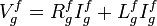
Eq. 2: The equation of electrical equilibrium in the armature circuit

Eq. 3: Motor torque equation

With total impedance,  , neglected, the transfer function can be obtained by solving eq 3
  .
.
Eq. 4: Transfer function
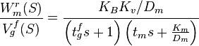
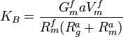
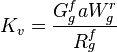
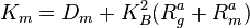
with the constants defined as below:


See also
- Adjustable-speed drive
- Amplidyne
- Brushed DC electric motor
- Electric motor
- Electronic speed control
- Harry Ward Leonard
- Metadyne
- Motor controller
- Motor-generator
References
- Citations
- ↑ Kulkarni, A.B. (Oct 2000). "Energy consumption analysis for geared elevator modernization: upgrade from DC Ward Leonard system to AC vector controlled drive". Conference Record of the 2000 IEEE Industry Applications Conference 4. Institute of Electrical and Electronics Engineers. pp. 2066–2070.
- ↑ Shinners, Stanley M (1998). Modern Control System Theory. Wiley and Sons. p. 202. ISBN 978-0471249061.
- ↑ 3.0 3.1 Datta, A.K. (1973). "Computerless optimal control of Ward Leonard drive system". International Journal of Systems Science 4 (4): 671–678. doi:10.1080/00207727308920047.
- General references
- The Editors (Nov 1989). "Technology for Electrical Components". Power Transmission Design: 25–27.
- Ward Leonard, H. (1896). "Volts versus ohms - the speed regulation of electric motors". AIEE Trans. 13: 375–384.
- Gottlieb, I.M. (1994). Electric Motors & Control Techniques 2nd Edition. TAB Books.
- Malcolm Barnes (2003). Practical Variable Speed Drives and Power Electronics. Oxford: Newnes. pp. 20–21. ISBN 978-0-7506-5808-9.
