Transversal (instrument making)
Transversals are a geometric construction on a scientific instrument to allow a graduation to be read to a finer degree of accuracy. Transversals have been replaced in modern times by vernier scales.
History
Transversals were used at a time when finely graduated instruments were difficult to make. They were found on instruments starting in the early 14th century, but the inventor is unknown.[1] Their use on astronomical instruments only began in the late 16th century. Tycho Brahe used them and did much to popularize the technique. The technique began to die out once verniers became common in the late 18th century – over a century after Pierre Vernier introduced the technique.
In the interim between transversals and the vernier scale, the nonius system, developed by Pedro Nunes, was used. However, it was never in common use. Tycho also used nonius methods, but he appears to be the only prominent astronomer to do so.
Linear transversals

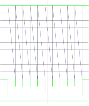
Black - grid lines
Blue - transversals
Green - instrument's graduations
Red - cursor line

Linear transversals were used on linear graduations. A grid of lines was constructed immediately adjacent to the linear graduations. The lines extending above the graduations formed part of the grid. The number of lines perpendicular to the extended graduation lines in the grid was dependent on the degree of fineness the instrument maker wished to provide. A grid of five lines would permit determination of the measure to one-fifth of a graduation's division. A ten-line grid would permit tenths to be measured. The distance between the lines is not critical as long as the distance is precisely uniform. Greater distances makes for greater accuracy.
As seen in the illustration on the right, once the grid was scribed, diagonals (transverse lines) were scribed from the uppermost corner of a column in the grid to the opposite lowest corner. This line intersects the cross lines in the grid in equal intervals. By using a cursor, alidade or similar indicator of measure, the closest point where the transversal crosses the grid is determined. That indicates the fraction of the graduation for the measure.
In the illustration, the reading is indicated by the vertical red line. This could be the edge of an alidade or a similar device. Since the cursor crosses the transversal closest to the fourth grid line from the top, the reading (assuming the leftmost long graduation line is 0.0) is 0.54.
Circular transversals
Circular transversals perform the same function as the linear ones but for circular arcs. In this case, the construction of the grid is significantly more complicated. A rectangular grid will not work. A grid of radial lines and circumferential arcs must be created. In addition, a linear transverse line will not divide the radial grid into equal segments. Circular arc segments must be constructed as transversals to provide the correct proportions.
See also
References
- ↑ Thomas Digges credits the 16th century clockmaker Richard Kantzler, however, as they've been used since the 14th century, this cannot be correct
- Daumas, Maurice, Scientific Instruments of the Seventeenth and Eighteenth Centuries and Their Makers, Portman Books, London 1989 ISBN 978-0-7134-0727-3