Section modulus
Section modulus is a geometric property for a given cross-section used in the design of beams or flexural members. Other geometric properties used in design include area for tension, radius of gyration for compression, and moment of inertia for stiffness. Any relationship between these properties is highly dependent on the shape in question. Equations for the section moduli of common shapes are given below. There are two types of section moduli, the elastic section modulus (S) and the plastic section modulus (Z).
Notation
North American and British/Australian convention reverse the usage of S & Z. Elastic modulus is S in North America,[1] but Z in Britain/Australia,[2] and vice versa for the plastic modulus. Eurocode 3 (EN 1993 - Steel Design) resolves this by using W for both, but distinguishes between them by the use of subscripts - Wel and Wpl.
Elastic section modulus
For general design, the elastic section modulus is used, applying up to the yield point for most metals and other common materials.
The elastic section modulus is defined as S = I / y, where I is the second moment of area (or moment of inertia) and y is the distance from the neutral axis to any given fibre.[3] It is often reported using y = c, where c is the distance from the neutral axis to the most extreme fibre, as seen in the table below. It is also often used to determine the yield moment (My) such that My = S × σy, where σy is the yield strength of the material.[3]
| Cross-sectional shape | Figure | Equation | Comment |
|---|---|---|---|
| Rectangle |  |
 |
Solid arrow represents neutral axis |
| doubly symmetric I-section (strong axis) |  |
 |
NA indicates neutral axis |
| doubly symmetric I-section (weak axis) |  |
 |
NA indicates neutral axis |
| Circle |  |
 [4] [4] |
Solid arrow represents neutral axis |
| Circular tube |  |
 |
Solid arrow represents neutral axis |
| Rectangular tube |  |
|
NA indicates neutral axis |
| Diamond |  |
 |
NA indicates neutral axis |
| C-channel |  |
|
NA indicates neutral axis |
Plastic section modulus
The Plastic section modulus is used for materials where (irreversible) plastic behaviour is dominant. The majority of designs do not intentionally encounter this behaviour.
The plastic section modulus depends on the location of the plastic neutral axis (PNA). The PNA is defined as the axis that splits the cross section such that the compression force from the area in compression equals the tension force from the area in tension. So, for sections with constant yielding stress, the area above and below the PNA will be equal, but for composite sections, this is not necessarily the case.
The plastic section modulus is then the sum of the areas of the cross section on each side of the PNA (which may or may not be equal) multiplied by the distance from the local centroids of the two areas to the PNA:

| Description | Figure | Equation | Comment |
|---|---|---|---|
| Rectangular section | |
 |
|
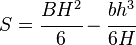
| Hollow rectangular section |  |
where: b=width, h=height, t=wall thickness | |
| For the two flanges of an I-beam with the web excluded |  |
,[5]
where:
| |
| For an I Beam including the web |  |
[6] | |
| For an I Beam (weak axis) |  |
||
| Solid Circle |  |
||
| Hollow Circle |  |
||
 =width,
  =thickness,
 are the distances from the neutral axis to the centroids of the flanges respectively.
The plastic section modulus is used to calculate the plastic moment, Mp, or full capacity of a cross-section. The two terms are related by the yield strength of the material in question, Fy, by Mp=Fy*Z. Sometimes Z and S are related by defining a 'k' factor which is something of an indication of capacity beyond first yield. k=Z/S
Therefore for a rectangular section, k=1.5
Use in structural engineering
Though generally section modulus is calculated for the extreme tensile or compressive fibres in a bending beam, often compression is the most critical case due to onset of flexural torsional buckling. Generally (except for brittle materials like concrete) tensile extreme fibres have a higher allowable stress or capacity than compressive fibres.
In the case of T-sections if you have tensile fibres at the bottom of the T they may still be more critical than the compressive fibres at the top due to a generally much larger distance from the neutral axis so despite having a higher allowable the elastic section modulus is also lower. In this case F/T buckling must still be assessed as the beam length and restraints may result in reduced compressive member bending allowable stress or capacity.
There may also be a number of different critical cases that require consideration, such as there being different values for orthogonal and principal axes and in the case of unequal angle sections in the principal axes there is a section modulus for each corner.
For a conservative (safe) design, civil structural engineers are often concerned with the combination of the highest load (tensile or compressive) and lowest elastic section modulus for a given section station along a beam, although if the loading is well understood you can take advantage of different section modulus for tension and compression to get more out of the design. For aeronautical and space applications where designs must be much less conservative for weight saving, structural testing is often required to ensure safety as reliance on structural analysis alone is more difficult (and expensive) to justify.
See also
- Beam theory
- List of area moments of inertia
- Second moment of area
References
- ↑ Specification for Structural Steel Buildings. Chicago, Illinois: American Institute of Steel Construction, Inc. 2010. p. 16.1–xxxiv.
- ↑ AS4100 - Steel Structures. Sydney, Australia: Standards Australia. 1998. p. 21.
- ↑ 3.0 3.1 Kulak, G.L. and Grondin, G.Y., 2006, Limit States Design in Structural Steel 8th Ed., Canadian Institute of Steel Construction.
- ↑ 4.0 4.1 Gere, J. M. and Timoshenko, S., 1997, Mechanics of Materials 4th Ed., PWS Publishing Co.
- ↑ American Institute of Steel Construction: Load and Resistance Factor Design, 3rd Edition, pp. 17-34.
- ↑ Megson, T H G (2005). Structural and stress analysis. elsever. pp. 598 EQ (iv).
External links
- http://www.engineeringtoolbox.com/american-wide-flange-steel-beams-d_1318.html - List of section moduli for common beam shapes
- http://www.novanumeric.com/samples.php?CalcName=SectionModulus - Online Calculation for Section Modulus