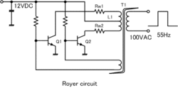
Royer oscillator
A Royer oscillator is an electronic oscillator circuit based on a relaxation oscillation, saturable-core transformer. It is used for DC to AC low frequency inverters. It was invented and patented in 1954 by George H. Royer.[1] It has the advantages of simplicity, low component count, rectangle waveforms and easy transformer isolation.
Circuit description

The circuit consists of a saturable-core transformer with a center-tapped primary winding, a feedback winding and (optionally) a secondary winding. The two halves of the primary are driven by two transistors in push-pull configuration. The feedback winding couples a small amount of the transformer flux back in to the transistor bases to provide positive feedback, generating oscillation. The oscillation frequency is determined by the maximum magnetic flux density, the power supply voltage, and the inductance of the primary winding.
The need to use a saturable-core limits the choice of core material. Some common materials are:
| Core material | Saturation Flux Density / G | Core Losses W/cm3 at 50 kHz |
|---|---|---|
| Toshiba MB | 6000 | 0.49 |
| Metglas2714A | 6000 | 0.62 |
| Square Permalloy 80 (0.5 mil) | 7800 | 0.98 |
| Square Permalloy 80 (1 mil) | 7800 | 4.2 |
| Fairite Type 84 | 4000 | 4 |
Current mode operation
A drawback of the voltage mode operation is that the stress on switch transistors is high during the cross over time, when both the voltage and current are high. This drawback is alleviated by using current mode operation. This is achieved by inserting an inductor in the transformer center tap supply. This inductor drops the center tap voltage down when the dI/dt would be very high in voltage mode.
Applications

The Royer oscillator circuit is used in DC–AC inverters. It relies solely on transformer core saturation to cause switching between the two states, unlike the similar "collector resonance" circuit assigned to Bell Telephone Laboratories [2] and P.J.Baxandall[3] which is commonly used to drive cold cathode fluorescent lamp (CCFL) backlights for LCD displays. CCFL inverters produce a sinusoidal waveform to maximize efficiency and battery life in portable equipment, and which is used in switching power supply and converter applications such as flyback transformers and power supplies.
External links
- Description of oscillator on HVWiki
- "Who was Royer and what did he invent?" (Appendix K) in Jim Williams, "A fourth generation of LCD backlight technology: Component and measurement improvements refine performance", Linear Technology Application Note 65, November 1995.
- By whom the collector resonance circuit was invented?,International Convention on Transistors and Associated Semiconductor Devices, 25th May, 1959/Transistor Sine-Wave LC Oscllators
References
- ↑ Royer oscillator circuit United States Patent 2783384
- ↑ United States Patent 3818314
- ↑ International Convention on Transistors and Associated Semiconductor Devices, 25th May, 1959/Transistor Sine-Wave LC Oscllators