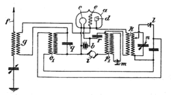
Reflectional receiver

A reflectional radio receiver (also called a reflex radio) is a radio receiver design in which the same amplifier is used for both the high-frequency radio (RF) and low-frequency sound (AF) signals. The radio signal from the output of the amplifier passes detection and then re-enters the input of the amplifier. During the second pass, the sound frequency is amplified then passed to the earphone. The German company Telefunken applied the German patent 293300 in the year 1913 for the reflex receiver.
The output of the amplifier is usually terminated by the radio frequency transformer. The amplified radio signal is taken from the secondary winding of the transformer k, passes detection (by the diode l in the given example) and then enters the same amplifier again as the low frequency signal through transformer o1. The amplified AF signal passes through transformer p1 to the earphone.
.png)
Reflectional radio receivers were used because fewer amplifier devices are needed. The 4 tubes General Electric superheterodyne receiver F40 used one tube for RF and AF amplification. They also consume less electricity than a receiver designed with two separate amplifiers. However, this design is less stable, with the possibility of breaking into unwanted oscillation. A greater level of skill and experience is needed to debug the assembled device before it starts working. In the schematic to the right, the value of the resistor R1 must be carefully chosen by hand because of variations in current gain between triodes of the same part number.
For a reflex circuit to work properly, bypassing and filtering are major considerations; also, it is important to insure the signal is AT ALL TIMES entirely operating within the linear range of the amplifier, or else inter-modulation (IM) will occur. It is difficult to judge when minor amounts of non-linearity occur in an amplifier. A reflex circuit will immediately produce severe distortion and possible oscillation as soon as the signal exceeds the linear range of the active component's curves, as this is the circumstance where the active device begins to work as a detector, which means it is mixing signal with the AF being fed back to amplify. This adds considerable difficulty to the making of a circuit which is dependably free of problems for all signals available. Problems are most common with large signals. LAYOUT considerations are critical in order to avoid unwanted coupling of RF signal back to the input; chokes should be toroid, not linear in physical construction, to avoid magnetic coupling for instance, and capacitive coupling must be prevented with careful layout, possibly including interleaving ground leads on PC board layout, or by using shielded wiring for hand wired circuits. The experimenter may care to employ a double sided printed circuit board, with one side being a ground plane, and connections laid out on the other side. However, if done properly, a reflex receiver can astound one with its sensitivity and gain with minimal component count. One example on the web gives drives a speaker with enough volume level for comfortable listening with only one transistor. The experimenter does well to try such a circuit, which is very under represented in modern experimental electronics literature. The use of reverse feedback at the DC level with appropriate decoupling filtering in the loop will help insure stability by self adjusting the bias level automatically; adjustment to the correct point consists of adjusting the trim pots of the bias feedback loop to insure correct biasing for linear operation.
External links
| Wikimedia Commons has media related to Reflectional circuits. |
- Schematic of FADA model 160 neutrodyne radio, a reflectional receiver from the 1920s.
- Schematic of General Electric model F40 radio, a reflectional receiver first manufactured in 1937.