RONJA


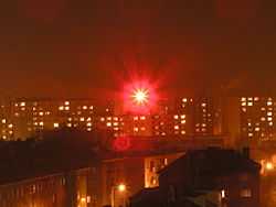
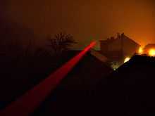
RONJA (Reasonable Optical Near Joint Access) is a free-space optical communication system originating in the Czech Republic. It transmits data wirelessly using beams of light. Ronja can be used to create a 10 Mbit/s full duplex Ethernet point-to-point link.
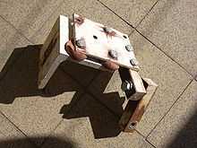
The range of the basic configuration is 1.4 km (0.87 mi). The device consists of a receiver and transmitter pipe (optical head) mounted on a sturdy adjustable holder. Two coaxial cables are used to connect the rooftop installation with a protocol translator installed in the house near a computer or switch. The range can be extended to 1.9 km (1.2 mi) by doubling or tripling the transmitter pipe.
Building instructions, blueprints, and schematics are published under the GNU Free Documentation Licence. Only free software tools are used in the development. The author calls this level of freedom "User Controlled Technology". Ronja is a project of Twibright Labs.
Manufacture
The building instructions are written with an inexperienced builder in mind. Basic operations like drilling, soldering etc., are explained. Several techniques - drilling templates, detailed checks after soldering, testing procedures - are employed to minimize errors at critical places and help to speed up work. Printed circuit boards are downloadable ready for manufacture, with instructions for the fabhouse. People with no previous experience with building electronics have reported on the mailing list that the device ran on the first try.
Around 153 installations worldwide have been registered into a gallery.
Models
- Ronja Tetrapolis: Range of 1.4 km (0.87 mi), red visible light. Connect with 8P8C connector into a network card or switch.
- Ronja 10M Metropolis: Range of 1.4 km (0.87 mi), red visible light. Connects to Attachment Unit Interface.
- Ronja Inferno: Range of 1.25 km (0.78 mi), invisible infrared light.
- Ronja Benchpress: A measurement device for developers for physical measurement of lens/LED combination gain and calculation of range from that
- Ronja Lopipe: The original (discontinued) design using red visible light and a RS232 interface for a max 115 kbit/s PPP/SLIP link.
Limitations
By definition, clear visibility between the transmitter and receiver are essential. If the beam is obscured in any way, the link will stop working. Typically, problems may occur during conditions of snow or dense fog.
Technology
System Overview
A complete RONJA system is made up of 2 transceivers: 2 optical transmitters and 2 optical receivers. They are assembled individually or as a combination. The complete system layout is shown in the block diagram.

Optical Receiver - Preamplifier stage

The usual approach in FSO (Free Space Optics) preamplifiers is to employ a transimpedance amplifier. A transimpedance amplifier is a very sensitive broadband high-speed device featuring a feedback loop. This fact means the layout is plagued with stability problems and special compensation of PIN diode capacitance must be performed, therefore this doesn't allow selection of a wide range of cheap PIN photodiodes with varying capacitances.
Ronja however uses a feedbackless design where the PIN has a high working electrical resistance (100 kilohms) which together with the total input capacitance (roughly 7 pF, 5 pF PIN and 2 pF input MOSFET cascode) makes the device operate with a passband on a 6 dB/oct slope of low pass formed by PIN working resistance and total input capacitance. The signal is then immediately amplified to remove the danger of contamination by signal noise, and then a compensation of the 6 dB/oct slope is done by derivator element on the programming pins of an NE592 video amplifier. A surprisingly flat characteristic is obtained. If the PIN diode is equipped with 3 kΩ working resistor to operate in flat band mode, the range is reduced to about 30% due to thermal noise from the 3 kΩ resistor.
Optical Transmitter - Nebulus infrared LED driver
The HSDL4220 infrared LED is originally unsuitable for 10 Mbit/s operation. It has a bandwidth of 9 MHz, where 10 Mbit/s Manchester-modulated systems need bandwidth of around 16 MHz. Operation in a usual circuit with current drive would lead to substantial signal corruption and range reduction. Therefore Twibright Labs developed a special driving technique consisting of driving the LED directly with 15-fold 74AC04 gate output in parallel without any current limitation. As the voltage to keep the nominal LED average current (100mA) varies with temperature and other component characteristic, an AC-bypassed current sense resistor is put in series with the LED. A feedback loop measures voltage on this resistor and keeps it at a preset level by varying supply voltage of the 74AC04 gates. Therefore the 74AC04 is operating as a structured power CMOS switch completely in analog mode.
This way the LED junction is flooded and cleared of carriers as quickly as possible, basically by short circuit discharge. This pushes the speed of the LED to maximum, which makes the output optical signal fast enough so that the range/power ratio is the same as with the faster red HPWT-BD00-F4000 LED. The side effects of this brutal driving technique are: 1) the LED overshoots at the beginning of longer (5 MHz/1 MHz) impulses to about 2x brightness. This was measured to have no adverse effect on range. 2) A blocking ceramic capacitor bank backing up the 74AC04 switching array is crucial for correct operation, because charging and discharging the LED is done by short circuit. Under dimensioning this bank causes the leading and trailing edges of the optical output to grow longer.
Transceiver - Ronja Twister
Ronja Twister is an electronic interface for free space optical datalink based on counter and shift register chips. It is a part of the Ronja design. It is effectively an optical Ethernet transceiver without the optical drive part.[1]
The original design has been superseded with Twister2 but the logic circuit remained the same.[2]
Organization
The whole toolchain is built strictly upon free tools and the source files are provided, free, under the GPL. This allows anyone to enter the development, start manufacture or invest into the technology without entry costs. Such costs normally can include software licence costs, time investment into resolution of compatibility issues between proprietary applications, or costs of intellectual property licence negotiations. The decision to conceive the project this way was inspired by observed organizational efficiency of Free Software.
In Christmas 2001, Ronja became the world's first 10 Mbit/s Free Space Optics device with free sources.
Examples of tools used in development:
- gEDA gschem (Schematic capture)[3]
- QCad
- BRL-CAD
- The PCB program[4]
- Sodipodi for Vector graphics
See also
- Wireless community network
- Visible light communication
- List of device bandwidths
References
- ↑ Ronja Twister
- ↑ Ronja Twister2
- ↑ Schematic capture
- ↑ PCB, Sourceforge
- Andy Oram (February 19, 2007), Ronja at 10 Mbit/s, the next stage in wireless mesh networking?, O'Reilly Emerging Telephony
- Unstrung: Da Doo Ron RONJA
- Ronja talk at WSFII London 2005 (archive.org)
- Hack a Day: Ronja
- A user testimonial
External links
| Wikimedia Commons has media related to RONJA. |
- ronja.twibright.com — Ronja Homepage
- Gallery of Registered Installations
- RONJA Adaptation for Underwater
- British council project - Promotion of ronja in community networks in UK 2004