Precession
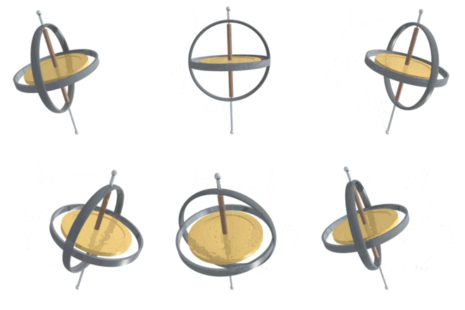
Precession is a change in the orientation of the rotational axis of a rotating body. In an appropriate reference frame it can be defined as a change in the first Euler angle, whereas the third Euler angle parameterizes the rotation itself. In other words, the axis of rotation of a precessing body itself rotates around another axis. A motion in which the second Euler angle changes is called nutation. In physics, there are two types of precession: torque-free and torque-induced.
In astronomy, "precession" refers to any of several slow changes in an astronomical body's rotational or orbital parameters, and especially to the Earth's precession of the equinoxes. See Astronomy section (below).
Torque-free
Torque-free precession occurs when the axis of rotation differs slightly from an axis about which the object can rotate stably: a maximum or minimum principal axis. Poinsot's construction is an elegant geometrical method for visualizing the torque-free motion of a rotating rigid body. For example, when a plate is thrown, the plate may have some rotation around an axis that is not its axis of symmetry. This occurs because the angular momentum (L) is constant in absence of torques. Therefore, it will have to be constant in the external reference frame, but the moment of inertia tensor (I) is non-constant in this frame because of the lack of symmetry. Therefore, the spin angular velocity vector ( ) about the spin axis will have to evolve in time so that the matrix product
  remains constant.
When an object is not perfectly solid, internal vortices will tend to damp torque-free precession, and the rotation axis will align itself with one of the inertia axes of the body.
The torque-free precession rate of an object with an axis of symmetry, such as a disk, spinning about an axis not aligned with that axis of symmetry can be calculated as follows:
where  is the precession rate,
  is the spin rate about the axis of symmetry,
  is the moment of inertia about the axis of symmetry, and
  is moment of inertia about either of the other two perpendicular principal axes. They should be the same, due to the symmetry of the disk.[1]
For a generic solid object without any axis of symmetry, the evolution of the object's orientation, represented (for example) by a rotation matrix  that transforms internal to external coordinates, may be numerically simulated. Given the object's fixed internal moment of inertia tensor
  and fixed external angular momentum
  , the instantaneous angular velocity is
  . Precession occurs by repeatedly recalculating
  and applying a small rotation vector
  for the short time
  ; e.g.,
 ![\scriptstyle {\boldsymbol R}_{{new}}\;=\;\exp([{\boldsymbol \omega }({\boldsymbol R}_{{old}})]_{{\times }}dt){\boldsymbol R}_{{old}}](/2014-wikipedia_en_all_02_2014/I/media/2/1/0/b/210b742e3ab69462a9131c8bee04f418.png) for the skew-symmetric matrix
for the skew-symmetric matrix ![\scriptstyle [{\boldsymbol \omega }]_{{\times }}](/2014-wikipedia_en_all_02_2014/I/media/4/4/2/a/442a56fd1a342feb008ff1a10fec0826.png) . The errors induced by finite time steps tend to increase the rotational kinetic energy,
. The errors induced by finite time steps tend to increase the rotational kinetic energy,  ; this unphysical tendency can be counter-acted by repeatedly applying a small rotation vector
  perpendicular to both
  and
and  , noting that
 ![\scriptstyle E(\exp([{\boldsymbol v}]_{{\times }}){\boldsymbol R})\;\approx \;E({\boldsymbol R})\,+\,({\boldsymbol \omega }({\boldsymbol R})\,\times \,{\boldsymbol L})\cdot {\boldsymbol v}](/2014-wikipedia_en_all_02_2014/I/media/1/a/7/8/1a78c73212fed03665ed453a37754532.png) .
.
Another type of torque-free precession can occur when there are multiple reference frames at work. For example, the earth is subject to local torque induced precession due to the gravity of the sun and moon acting upon the earth’s axis, but at the same time the solar system is moving around the galactic center. As a consequence, an accurate measurement of the earth’s axial reorientation relative to objects outside the frame of the moving galaxy (such as distant quasars commonly used as precession measurement reference points) must account for a minor amount of non-local torque-free precession, due to the solar system’s motion.
Torque-induced
Torque-induced precession (gyroscopic precession) is the phenomenon in which the axis of a spinning object (e.g., a part of a gyroscope) "wobbles" when a torque is applied to it, which causes a distribution of force around the acted axis. The phenomenon is commonly seen in a spinning toy top, but all rotating objects can undergo precession. If the speed of the rotation and the magnitude of the torque are constant, the axis will describe a cone, its movement at any instant being at right angles to the direction of the torque. In the case of a toy top, if the axis is not perfectly vertical, the torque is applied by the normal force of the ground pushing up on it.
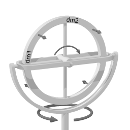
The device depicted on the right is gimbal mounted. From inside to outside there are three axes of rotation: the hub of the wheel, the gimbal axis, and the vertical pivot.
To distinguish between the two horizontal axes, rotation around the wheel hub will be called spinning, and rotation around the gimbal axis will be called pitching. Rotation around the vertical pivot axis is called rotation.
First, imagine that the entire device is rotating around the (vertical) pivot axis. Then, spinning of the wheel (around the wheelhub) is added. Imagine the gimbal axis to be locked, so that the wheel cannot pitch. The gimbal axis has sensors, that measure whether there is a torque around the gimbal axis.
In the picture, a section of the wheel has been named dm1. At the depicted moment in time, section dm1 is at the perimeter of the rotating motion around the (vertical) pivot axis. Section dm1, therefore, has a lot of angular rotating velocity with respect to the rotation around the pivot axis, and as dm1 is forced closer to the pivot axis of the rotation (by the wheel spinning further), because of the Coriolis effect dm1 tends to move in the direction of the top-left arrow in the diagram (shown at 45°) in the direction of rotation around the pivot axis. Section dm2 of the wheel starts out at the vertical pivot axis, and thus initially has zero angular rotating velocity with respect to the rotation around the pivot axis, before the wheel spins further. A force (again, a Coriolis force) would be required to increase section dm2's velocity up to the angular rotating velocity at the perimeter of the rotating motion around the pivot axis. If that force is not provided, then section dm2's inertia will make it move in the direction of the top-right arrow. Note that both arrows point in the same direction.
The same reasoning applies for the bottom half of the wheel, but there the arrows point in the opposite direction to that of the top arrows. Combined over the entire wheel, there is a torque around the gimbal axis when some spinning is added to rotation around a vertical axis.
It is important to note that the torque around the gimbal axis arises without any delay; the response is instantaneous.
In the discussion above, the setup was kept unchanging by preventing pitching around the gimbal axis. In the case of a spinning toy top, when the spinning top starts tilting, gravity exerts a torque. However, instead of rolling over, the spinning top just pitches a little. This pitching motion reorients the spinning top with respect to the torque that is being exerted. The result is that the torque exerted by gravity – via the pitching motion – elicits gyroscopic precession (which in turn yields a counter torque against the gravity torque) rather than causing the spinning top to fall to its side.
Precession or gyroscopic considerations have an effect on bicycle performance at high speed. Precession is also the mechanism behind gyrocompasses.
Gyroscopic precession also plays a large role in the flight controls on helicopters. Since the driving force behind helicopters is the rotor disk (which rotates), gyroscopic precession comes into play. If the rotor disk is to be tilted forward (to gain forward velocity), its rotation requires that the downward net force on the blade be applied roughly 90 degrees (depending on blade configuration) before that blade gets to the 12 o'clock position. This means the pitch of each blade will decrease as they pass through 3 o'clock, assuming the rotor blades are turning CCW as viewed from above looking down at the helicopter. The same applies if a banked turn to the left or right is desired; the pitch change will occur when the blades are at 6 and 12 o'clock, as appropriate. Whatever position the rotor disc needs to placed at, each blade must change its pitch to effect that change 90 degrees prior to reaching the position that would be necessary for a non-rotating disc.
To ensure the pilot's inputs are correct, the aircraft has corrective linkages that vary the blade pitch in advance of the blade's position relative to the swashplate. Although the swashplate moves in the intuitively correct direction, the blade pitch links are arranged to transmit the pitch in advance of the blade's position.
Classical (Newtonian)
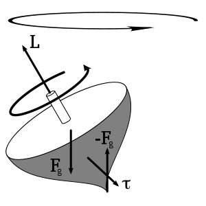
Precession is the result of the angular velocity of rotation and the angular velocity produced by the torque. It is an angular velocity about a line that makes an angle with the permanent rotation axis, and this angle lies in a plane at right angles to the plane of the couple producing the torque. The permanent axis must turn towards this line, since the body cannot continue to rotate about any line that is not a principal axis of maximum moment of inertia; that is, the permanent axis turns in a direction at right angles to that in which the torque might be expected to turn it. If the rotating body is symmetrical and its motion unconstrained, and, if the torque on the spin axis is at right angles to that axis, the axis of precession will be perpendicular to both the spin axis and torque axis.
Under these circumstances the angular velocity of precession is given by:
In which Is is the moment of inertia,  is the angular velocity of spin about the spin axis, and m*g and r are the force responsible for the torque and the perpendicular distance of the spin axis about the axis of precession. The torque vector originates at the center of mass. Using
  =
=  , we find that the period of precession is given by:
In which Is is the moment of inertia, Ts is the period of spin about the spin axis, and  is the torque. In general, the problem is more complicated than this, however.
There is a non-mathematical way of visualizing the cause of gyroscopic precession. The behavior of spinning objects simply obeys the law of inertia by resisting any change in direction. If a force is applied to the object to induce a change in the orientation of the spin axis, the object behaves as if that force was applied 90 degrees ahead, in the direction of rotation. Here is why: A solid object can be thought of as an assembly of individual molecules. If the object is spinning, each molecule's direction of travel constantly changes as that molecule revolves around the object's spin axis. When a force is applied, molecules are forced into a new change of direction at places during their path around the object's axis. This new change in direction is resisted by inertia.
Imagine the object to be a spinning bicycle wheel, held at the axle in the hands of a subject. The wheel is spinning clock-wise as seen from a viewer to the subject’s right. Clock positions on the wheel are given relative to this viewer. As the wheel spins, the molecules comprising it are travelling vertically downward the instant they pass the 3 o'clock position, horizontally to the left the instant they pass 6 o'clock, vertically upward at 9 o'clock, and horizontally right at 12 o'clock. Between these positions, each molecule travels a combination of these directions, which should be kept in mind as you read ahead. If the viewer applies a force to the wheel at the 3 o'clock position, the molecules at that location are not being forced to change direction; they still travel vertically downward, unaffected by the force. The same goes for the molecules at 9 o'clock; they are still travelling vertically upward, unaffected by the force that was applied. But, molecules at 6 and 12 o'clock ARE being "told" to change direction. At 6 o'clock, molecules are forced to veer toward the viewer. At the same time, molecules that are passing 12 o'clock are being forced to veer away from the viewer. The inertia of those molecules resists this change in direction. The result is that they apply an equal and opposite force in response. At 6 o'clock, molecules exert a push directly away from the viewer. Molecules at 12 o'clock push directly toward the viewer. This all happens instantaneously as the force is applied at 3 o'clock. This makes the wheel as a whole tilt toward the viewer. Thus, when the force was applied at 3 o'clock, the wheel behaved as if the force was applied at 6 o'clock – 90 degrees ahead in the direction of rotation.
Precession causes another peculiar behavior for spinning objects such as the wheel in this scenario. If the subject holding the wheel removes one hand from the axle, the wheel will remain upright, supported from only one side. However, it will immediately take on an additional motion; it will begin to rotate about a vertical axis, pivoting at the point of support as it continues its axial spin. If the wheel was not spinning, it would topple over and fall if one hand was removed. The initial motion of the wheel beginning to topple over is equivalent to applying a force to it at 12 o'clock in the direction of the unsupported side. When the wheel is spinning, the sudden lack of support at one end of the axle is again equivalent to this force. So instead of toppling over, the wheel behaves as if the force was applied at 3 or 9 o’clock, depending on the direction of spin and which hand was removed. This causes the wheel to begin pivoting at the point of support while remaining upright.
Relativistic
The special and general theories of relativity give three types of corrections to the Newtonian precession, of a gyroscope near a large mass such as the earth, described above. They are:
- Thomas precession a special relativistic correction accounting for the observer's being in a rotating non-inertial frame.
- de Sitter precession a general relativistic correction accounting for the Schwarzschild metric of curved space near a large non-rotating mass.
- Lense-Thirring precession a general relativistic correction accounting for the frame dragging by the Kerr metric of curved space near a large rotating mass.
Astronomy
In astronomy, precession refers to any of several gravity-induced, slow and continuous changes in an astronomical body's rotational axis or orbital path. Precession of the equinoxes, perihelion precession, changes in the tilt of the Earth's axis to its orbit, and the eccentricity of its orbit over tens of thousands of years are all important parts of the astronomical theory of ice ages.
Axial precession (precession of the equinoxes)
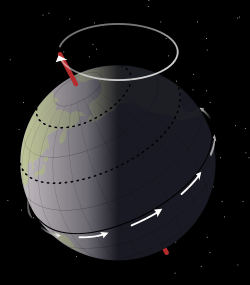
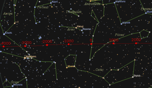

Axial precession is the movement of the rotational axis of an astronomical body, whereby the axis slowly traces out a cone. In the case of Earth, this type of precession is also known as the precession of the equinoxes, lunisolar precession, or precession of the equator. Earth goes through one such complete precessional cycle in a period of approximately 26,000 years or 1° every 72 years, during which the positions of stars will slowly change in both equatorial coordinates and ecliptic longitude. Over this cycle, Earth's north axial pole moves from where it is now, within 1° of Polaris, in a circle around the ecliptic pole, with an angular radius of about 23.5 degrees.
Hipparchus is the earliest known astronomer to recognize and assess the precession of the equinoxes at about 1° per century (which is not far from the actual value for antiquity, 1.38°).[2] The precession of Earth's axis was later explained by Newtonian physics. Being an oblate spheroid, the Earth has a nonspherical shape, bulging outward at the equator. The gravitational tidal forces of the Moon and Sun apply torque to the equator, attempting to pull the equatorial bulge into the plane of the ecliptic, but instead causing it to precess. The torque exerted by the planets, particularly Jupiter, also plays a role.[3]
Perihelion precession

The orbit of a planet around the Sun is not really an ellipse but a flower-petal shape because the major axis of each planet's elliptical orbit also precesses within its orbital plane, partly in response to perturbations in the form of the changing gravitational forces exerted by other planets. This is called perihelion precession or apsidal precession.
Discrepancies between the observed perihelion precession rate of the planet Mercury and that predicted by classical mechanics were prominent among the forms of experimental evidence leading to the acceptance of Einstein's Theory of Relativity (in particular, his General Theory of Relativity), which accurately predicted the anomalies.[4][5]Deviating from Newton's law, Einstein's theory of gravitation predicts an extra term of A/r4, which accurately gives the observed excess turning rate of 43 arcseconds every 100 years.
The gravitational force between the Sun and moon induces the precession in the Earth's orbit, which is the major cause of the widely known climate oscillation of Earth that has a period of 19,000 to 23,000 years. The changes in the parameters (e.g. orbital inclination, the angle between Earth's rotation axis and revolution orbit ) of the orbit of Earth is an important field in the study of Ice Age in the theoretical astronomy.
See also nodal precession. For precession of the lunar orbit see lunar precession.
See also
| Wikimedia Commons has media related to Precession. |
References
- ↑ Boal, David (2001). "Lecture 26 – Torque-free rotation – body-fixed axes". Retrieved 2008-09-17.
- ↑ DIO 9.1 ‡3
- ↑ Bradt, Hale (2007). Astronomy Methods. Cambridge University Press. p. 66. ISBN 978 0 521 53551 9.
- ↑ Max Born (1924), Einstein's Theory of Relativity (The 1962 Dover edition, page 348 lists a table documenting the observed and calculated values for the precession of the perihelion of Mercury, Venus, and Earth.)
- ↑ An even larger value for a precession has been found, for a black hole in orbit around a much more massive black hole, amounting to 39 degrees each orbit.
External links
| Wikibooks has a book on the topic of: Rotational Motion |
- Explanation and derivation of formula for precession of a top
- Precession and the Milankovich theory from educational web site From Stargazers to Starships


