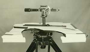
Plane table
A plane table (plain table prior to 1830)[1] is a device used in surveying and related disciplines to provide a solid and level surface on which to make field drawings, charts and maps. The early use of the name plain table reflected its simplicity and plainness rather than its flatness.[2]
History
The earliest mention of a plane table dates to 1551 in Abel Foullon's "Usage et description de l'holomètre", published in Paris.[3] However, since Foullon's description was of a complete, fully developed instrument, it must have been invented earlier.[2]
A brief description was also added to the 1591 edition of Digge's Pantometria.[3] The first mention of the device in English was by Cyprian Lucar in 1590.[1]
Some have credited Johann Richter, also known as Johannes Praetorius,[4] a Nuremberg mathematician, in 1610[5] with the first plane table, but this appears to be incorrect.
The plane table became a popular instrument for surveying.[2] Its use was widely taught. Interestingly, there were those who considered it a substandard instrument compared to such devices as the theodolite, since it was relatively easy to use.[1] By allowing the use of graphical methods rather than mathematical calculations, it could be used by those with less education than other instruments.
Plane table construction

This shows a plane table with part of the surface of the table cut away to show the mounting on the tripod. The mount allows the table to be levelled. On the table, the alidade with telescopic sight is seen
Use of a plane table
In use, a plane table is set over a point and brought to precise horizontal level. A drawing sheet is attached to the surface and an [alidade] is used to sight objects of interest. The alidade, in modern examples of the instrument a [ruler|rule] with a [telescopic sight], can then be used to construct a line on the drawing that is in the direction of the object of interest.
By using the alidade as a surveying level, information on the topography of the site can be directly recorded on the drawing as elevations. Distances to the objects can be measured directly or by the use of [stadia mark]s in the telescope of the alidade.
References
- ↑ 1.0 1.1 1.2 Turner, Gerard L'E., Scientific Instruments 1500-1900, An Introduction, University of California Press, 1998 ISBN 0-85667-491-5. This is an updated version of his earlier Antique Scientific Instruments Blandford Press Ltd. 1980, ISBN 0-7137-1068-3
- ↑ 2.0 2.1 2.2 Kiely, Edmond, Surveying Instruments: Their history and classroom use, Bureau of Publications, Teachers College, Columbia University, 1947. page 228
- ↑ 3.0 3.1 Turner, Anthony, Early Scientific Instruments, Europe 1400-1800, Sotheby's Publishing, 1987, ISBN 0-85667-319-6. page 81
- ↑ Vai, Gian Battista, Caldwell, W. G. E. The Origins of Geology in Italy Google books online copy
- ↑ Laussedat, Amié, Recherches sur les instruments, les méthodes et le dessin topographiques, Paris, 1898-1902, two volumes
- Raymond Davis, Francis Foote, Joe Kelly, Surveying, Theory and Practice, McGraw-Hill Book Company, 1966 LC 64-66263
External links
- Telescopic Plane Table Alidade in the collection of the Smithsonian National Museum of American History. This image shows the bubble levels on the base.
- http://www.sciencemuseum.org.uk/objects/surveying/1933-7.aspx