Neutral axis

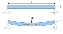
The neutral axis is an axis in the cross section of a beam (a member resisting bending) or shaft along which there are no longitudinal stresses or strains. If the section is symmetric, isotropic and is not curved before a bend occurs, then the neutral axis is at the geometric centroid. All fibers on one side of the neutral axis are in a state of tension, while those on the opposite side are in compression
Since the beam is undergoing uniform bending, a plane on the beam remains plane. That is:

Where  is the shear strain and
  is the shear stress
There is a compressive (negative) strain at the top of the beam, and a tensile (positive) strain at the bottom of the beam. Therefore by the Intermediate Value Theorem, there must be some point in between the top and the bottom that has no strain, since the strain in a beam is a continuous function.
Let L be the original length of the beam (span)
ε(y) is the strain as a function of coordinate on the face of the beam.
σ(y) is the stress as a function of coordinate on the face of the beam.
ρ is the radius of curvature of the beam at its neutral axis.
θ is the bend angle
Since the bending is uniform and pure, there is therefore at a distance y from the neutral axis with the inherent property of having no strain:

Therefore the longitudinal normal strain  varies linearly with the distance y from the neutral surface. Denoting
  as the maximum strain in the beam (at a distance c from the neutral axis), it becomes clear that:

Therefore, we can solve for ρ, and find that:

Substituting this back into the original expression, we find that:

Due to Hooke's Law, the stress in the beam is proportional to the strain by E, the modulus of Elasticity:

Therefore:


From statics, a moment (i.e. pure bending) consists of equal and opposite forces. Therefore, the total amount of force across the cross section must be 0.

Therefore:

Since y denotes the distance from the neutral axis to any point on the face, it is the only variable that changes with respect to dA. Therefore:

Therefore the first moment of the cross section about its neutral axis must be zero. Therefore the neutral axis lies on the centroid of the cross section.
Note that the neutral axis does not change in length when under bending. It may seem counterintuitive at first, but this is because there are no bending stresses in the neutral axis. However, there are shear stresses (τ) in the neutral axis, zero in the middle of the span but increasing towards the supports, as can be seen in this function (Jourawski's formula);
where
T = shear force
Q = first moment of area of the section above/below the neutral axis
w = width of the beam
I = second moment of area of the beam
This definition is suitable for the so-called long beams, i.e. its length is much larger than the other two dimensions.
Arches
Arches also have a neutral axis. If they are made of stone; stone is an inelastic medium, and has little strength in tension. Therefore as the loading on the arch changes the neutral axis moves- if the neutral axis leaves the stonework, then the arch will fail.
This theory (also known as the thrust line method) was proposed by Thomas Young and developed by Isambard Kingdom Brunel.
See also
- Second moment of inertia
