Magnetoresistance
Magnetoresistance is the property of a material to change the value of its electrical resistance when an external magnetic field is applied to it. The effect was first discovered by William Thomson (better known as Lord Kelvin) in 1851, but he was unable to lower the electrical resistance of anything by more than 5%. This effect was later called ordinary magnetoresistance (OMR). More recent researchers discovered materials (and multilayer devices) showing giant magnetoresistance (GMR), colossal magnetoresistance (CMR) and tunnel magnetoresistance (TMR). Generally, resistance can depend either on magnetization (controlled by applied magnetic field) or on magnetic field directly.
Discovery
William Thomson (Lord Kelvin) first discovered ordinary magnetoresistance in 1851. He experimented with pieces of iron and discovered that the resistance increases when the current is in the same direction as the magnetic force and decreases when the current is at 90° to the magnetic force. He then did the same experiment with nickel and found that it was affected in the same way but the magnitude of the effect was greater. This effect is referred to as anisotropic magnetoresistance (AMR).

Geometrical magnetoresistance
An example of magnetoresistance due to direct action of magnetic field on electric current can be studied on a Corbino disc (see Figure). It consists of a conducting annulus with perfectly conducting rims. Without a magnetic field, the battery drives a radial current between the rims. When a magnetic field parallel to the axis of the annulus is applied, a circular component of current flows as well, due to the Lorentz force. A discussion of the disc is provided by Giuliani.[1] Initial interest in this problem began with Boltzmann in 1886, and independently was re-examined by Corbino in 1911.[1]
In a simple model, supposing the response to the Lorentz force is the same as for an electric field, the carrier velocity v is given by:

where μ = carrier mobility. Solving for the velocity, we find:

where the reduction in mobility due to the B-field is apparent. Electric current (proportional to the radial component of velocity) will decrease with increasing magnetic field and hence the resistance of the device will increase. This magnetoresistive scenario depends sensitively on the device geometry and current lines and it does not rely on magnetic materials.
In a semiconductor with a single carrier type, the magnetoresistance is proportional to (1 + (μB)2), where μ is the semiconductor mobility (units m2·V−1·s−1 or T −1) and B is the magnetic field (units teslas). Indium antimonide, an example of a high mobility semiconductor, could have an electron mobility above 4 m2·V−1·s−1 at 300 K. So in a 0.25 T field, for example the magnetoresistance increase would be 100%.
Anisotropic magnetoresistance (AMR)

In polycrystalline ferromagnetic materials, the AMR can only depend on the angle  between the magnetization and current direction
and (as long as the resistivity of the material can be described by a rank-two tensor), it must follow[5]
between the magnetization and current direction
and (as long as the resistivity of the material can be described by a rank-two tensor), it must follow[5]
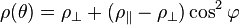
where  is the (longitudinal) resistivity of the film and
  are the resistivities for
  and
and  , respectively. Associated with longitudinal resistivity, there is also transversal resistivity dubbed (somewhat confusingly[1]) the planar Hall effect. In monocrystals, resistivity depends also on
  individually.
To compensate for the non-linear characteristics and inability to detect the polarity of a magnetic field, the following structure is used for sensors. It consists of stripes of aluminum or gold placed on a thin film of permalloy (a ferromagnetic material exhibiting the AMR effect) inclined at an angle of 45°. This structure forces the current not to flow along the “easy axes” of thin film, but at an angle of 45°. The dependence of resistance now has a permanent offset which is linear around the null point. Because of its appearance, this sensor type is called 'barber pole'.
The AMR effect is used in a wide array of sensors for measurement of Earth's magnetic field (electronic compass), for electric current measuring (by measuring the magnetic field created around the conductor), for traffic detection and for linear position and angle sensing. The biggest AMR sensor manufacturers are Honeywell, NXP Semiconductors, and Sensitec GmbH.
Footnotes
- 1. The (ordinary) Hall effect changes sign upon magnetic field reversal and it is an orbital effect (unrelated to spin) due to the Lorentz force. Transversal AMR (planar Hall effect[6]) does not change sign and it is caused by spin-orbit interaction.
References
- ↑ 1.0 1.1 G Giuliani, (2008). "A general law for electromagnetic induction". EPS 81 (6): 60002. Bibcode:2008EL.....8160002G. doi:10.1209/0295-5075/81/60002.
- ↑ W. Thomson, Proc. Royal Soc. London,Vol. 8, (1856-1857), pp.546-550.
- ↑ McGuire, T.; Potter, R. (1975). "Anisotropic magnetoresistance in ferromagnetic 3d alloys". IEEE Transactions on Magnetics 11 (4): 1018. doi:10.1109/TMAG.1975.1058782.
- ↑ P. Wiśniewski, "Giant anisotropic magnetoresistance and magnetothermopower in cubic 3:4 uranium pnictides" (2007) http://dx.doi.org/10.1063/1.2737904
- ↑ E. de Ranieri et al., "Lithographically and electrically controlled strain effects on anisotropic magnetoresistance in (Ga,Mn)As", New J. Phys. 10, 065003 (2008). http://dx.doi.org/10.1088/1367-2630/10/6/065003
- ↑ H. X. Tang, R. K. Kawakami, D. D. Awschalom, and M. L. Roukes Phys. Rev. Lett. 90, 107201 (2003). http://dx.doi.org/10.1103/PhysRevLett.90.107201
See also
| Look up magnetoresistance in Wiktionary, the free dictionary. |
| Wikimedia Commons has media related to magnetoresistance. |