Helical scan


Helical scan is a method of recording high frequency signals on magnetic tape. It is used in reel-to-reel video tape recorders, video cassette recorders, digital audio tape recorders, and some computer tape drives.
Comparison to linear tape recording
In a fixed tape head system, magnetic tape is drawn past the head at a constant speed. The head creates a fluctuating magnetic field in response to the signal to be recorded, and the magnetic particles on the tape are forced to line up with the field at the head. As the tape moves away, the magnetic particles carry an imprint of the signal in their magnetic orientation. If the tape moves too slowly, a high frequency signal will not be imprinted: the particles' polarity will simply oscillate in the vicinity of the head, to be left in a random position. Thus the bandwidth channel capacity of the recorded signal can be seen to be related to tape speed: the faster the speed, the higher the frequency that can be recorded. The difference between the head writing speed and linear tape speed is vast: for example, 13 mph (5.8 m/s) versus 35 mm/s.
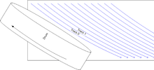
Digital video and digital audio need considerably more bandwidth than analog audio, so much so that tape would have to be drawn past the heads at very high speed to capture this signal. This is impractical, since tapes of immense length would be required. The generally-adopted solution is to rotate the head against the tape at high speed, so that the relative velocity is high, but the tape itself moves at a slow speed. To accomplish this, the head must be tilted so that at each rotation of the head, a new area of tape is brought into play. Each segment of the signal is recorded as a diagonal stripe across the tape. This is known as a helical scan because the tape wraps around the circular drum at an angle, travelling up like a helix.
History
The helical scan method of recording was first developed by engineers at Toshiba, in Japan.[1] With the advent of television broadcasting in Japan in the early 1950s, they saw the need for magnetic television signal recording just as engineers in the US and Europe did. When Ampex developed the first practical magnetic tape video recording system in 1956, known as quadruplex, it had certain limitations, perhaps the most important of which was the lack of "pause" or still frame capability. This limitation was due to the fact that the picture signal was "segmented," or broken down into discrete segments to be recorded on the tape individually (only 16 lines of the picture in each segment). Thus, when tape motion was stopped, only a single segment of the picture recording was present at the playback heads. The motivation to overcome this limitation lead, in part, to the development of the helical scan system.
Toshiba introduced helical scan technology to the television industry in 1959. During the 1960s, and 1970s, helical scan recording machines were introduced by many manufacturers and marketed all over the world. The technology rapidly took over the market for video recording, due to its reduced complexity, greater reliability, lower manufacturing & servicing costs, lighter weight, lower energy consumption, and more versatile features, when compared to the quadruplex system. These factors also made it possible eventually to bring video recording to users at home, in a cassette format.
Practical problems
There were a number of problems to be overcome with this system. The high tape/head speed could lead to rapid wear of both the tape and the head, so both need to be highly polished, and the head made of a hard, wear resistant material. Most systems operate with an air bearing separating the heads from the surface of the tape. Supplying signals to a rotating head is also problematic: This is usually accomplished by coupling the signal(s) inductively through a rotary transformer. The transport mechanism is also much more complex than a fixed head system, since during loading, the tape must be pulled around a rotating drum containing the head(s). In a VCR for example, the tape must be pulled out of the cassette case and threaded around the drum, and between the capstan and pinch roller. This leads to complex and potentially unreliable mechanics.
Transport systems
Two transport systems evolved in the early video machines, known as the alpha wrap and the omega wrap. In the alpha wrap machines the tape was wrapped around the head drum for a full 360 degrees (the tape looking like the lowercase Greek letter alpha). There was only one head which wrote a complete stripe for every revolution of the head. This system had problems when the head transited from one piece of tape to the next giving a large signal gap between fields. The machine had to fill this gap with the frame synchronizing pulses. Such machines were constrained to using guard band recording (see below).
In the omega wrap machines, the tape was only wrapped around the head for 180 degrees. Two video heads were required, each writing alternate fields. This system had a much smaller signal gap between fields, but the frame synchronizing pulses were able to be recorded on the tape. Cassette based systems could only utilize the omega wrap technique, since it was geometrically impossible for an automatic loading system to introduce a loop into the tape. Early omega wrap systems utilized guard band recording, but the presence of two heads permitted the development of the slant azimuth technique. Later developments used increasing numbers of heads to record video using smaller drums and for recording HiFi sound as well.
A variation of the omega wrap, such as that used by Echo Science Corporation of Mountain View, California in its instrumentation and high resolution video recorders in the late 1970s and 1980s, wrapped the 1-inch tape about 190 degrees around the two-headed drum, so there was signal overlap between the two heads. Head switching in video recorders occurred instantaneously in the video models, during an horizontal sync interval. With a standard NTSC video signal a head could cover one-sixth of a field each time it passed across the tape. Switching in instrumentation models was gradual, so the signals from both heads overlapped briefly, producing a transient-free output signal where the original signal did not contain convenient dead intervals during which a switching transient could be hidden.
Slant azimuth recording
Every videotape system attempts to pack as much video as possible onto a given-sized tape, but information from one recording stripe (pass of the video head) must not interfere with information on adjacent stripes. One method to provide isolation between the stripes is the use of guard bands (unrecorded areas between the stripes), but this wastes valuable tape space. All the early reel-to-reel machines and the first cassette formats, the Philips VCR and the Sony U-matic used this system.
Later helical scanning recorders instead usually use a method called slant azimuth recording, also called Symmetric Phase Recording. The head drum usually contains two heads with the magnetic gap of one head slanted slightly leftwards and the magnetic gap of the other head slanted slightly rightwards. (The slant of a magnetic head is referred to as its azimuth adjustment). Because of the alternating slants, each head will not wrongly read the signal recorded by the other head and the stripes can be recorded immediately next to each other, alternating between left slant on one television field and right slant on the next television field. (In practice, it's not uncommon for the recorded stripes to overlap somewhat). Later machines including the JVC VHS and the Sony Betamax used slant azimuth recording as well as all later machines and their digital derivatives.
Using slant azimuth recording, the need for guard bands is completely eliminated, allowing more recording to be placed on a given length of tape.
Contrast with quadruplex recording
Helical scanning was a logical progression beyond an earlier system (pioneered by Ampex) known as quadruplex recording, also referred to as transverse recording. In this scheme, the rotating head drum ran essentially perpendicular to a 2-inch-wide (51 mm) tape, and the slices recorded across the tape were nearly perpendicular to the tape's motion. U.S. quadruplex systems revolved the head drum at 14,400 revolutions per minute (240 revolutions per second) with four heads on the drum so that each television field was broken into sixteen stripes on the tape (which required appropriately complex head-switching logic). By comparison, the longer stripe recorded by a helical scan recorder usually contains an entire TV field and the two-headed head drum spins at the frame rate (half the field rate) of the TV system in use.
Recording an entire field in a single pass allowed these machines to play back a viewable still frame when the tape was stopped, and display a viewable image sequence while shuttling forwards or backwards. This greatly facilitated the editing process. The quadruplex systems were unable to display video from tape except while playing at normal speed.
Gallery
-

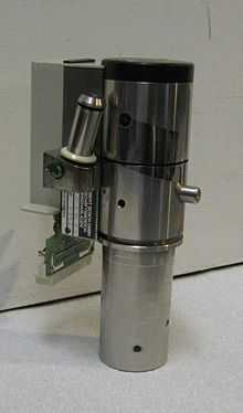
Type B videotape video scanner head
-

rotary head visible in a VXA computer tape drive
-

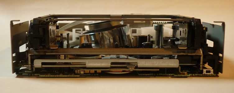
VXA tape drive, alternate view of rotary head and loading mechanism
See also
| Wikimedia Commons has media related to Helical scan tape heads. |
- Type A videotape
- 1 inch type B videotape
- 1 inch type C videotape
- IVC videotape format about the IVC 2 inch helical VTR, Model 9000
- Video tape recorder (VTR)
- Vision Electronic Recording Apparatus
- Ampex 2 inch helical VTR
- Symmetric Phase Recording
References
External links
- Information on a 1 inch Type C VTR, the Ampex VPR-1.
- Photos and comparison of various Sony U-matic decks.
- Sony U.S. patent for U-matic videotape cassette, filed 1971.
- Sony U.S. patent for design of U-matic deck, filed 1971.]
- - VPR-2
- Lab Guys World VR-1500
- Lab Guys World Ampex Cat
- Lab Guys World Ampex VR-1550 and VR-660
- Lab Guys World Ampex VR-660B
- Lion Lamb Ampex page
- Rewind Museum complete VR-1500 system add
- DC Video VR 660 page
- Tonband Museum
- video preservation and conservation us.org museum
- fundinguniverse.com Ampex History
- columbiaisa, Consumer & Professional Video Formats, Video Formats: history
- DC video VR-600 page
- Vintage Ad Browser. electronics ad for VR-1500
- Sony.com History Page
- Lab Guys World Sony Sony 2 inch helical VTR page
- The history of television, 1942 to 2000 By Albert Abramson, page 93.
- Link to a 1" Type A VTR, the Ampex VR-7300
- VPR-1 The last Type A VTR
- VidiPax Video Formats Guide
- Other one inch VTRs
- Ampex VR- VTRs
- DC Video operator of VR-7800
- Experimental TV Center Ampex page
| ||||||||||||||||||||||||||||||||||||||