Electronic symbol

An electronic symbol is a pictogram used to represent various electrical and electronic devices (such as wires, batteries, resistors, and transistors) in a schematic diagram of an electrical or electronic circuit. These symbols can (because of remaining traditions) vary from country to country, but are today to a large extent internationally standardized. Some symbols represent components which ceased to be used routinely as newer technologies were introduced (such as vacuum tubes).
Standards for symbols
There are several national and international standards for graphical symbols in circuit diagrams, in particular:
- IEC 60617 (also known as British Standard BS 3939)
- ANSI standard Y32 (also known as IEEE Std 315)
- Australian Standard AS 1102
Different symbols may be used depending on the discipline using the drawing. For example, lighting and power symbols used as part of architectural drawings may be different from symbols for devices used in electronics. National and local variations to international standards also exist.
Gallery of common electronic symbols
Symbols shown are typical examples, not a complete list.
Resistors
-
%2C_and_Potentiometer_symbols.svg.png)
American-style resistor (a), rheostat (variable resistor) (b), and potentiometer (c)
-

IEC-style resistor
Capacitors
-

Capacitor, polarized (American)


Transistors
-
.svg.png)
NPN transistor
-
.svg.png)
PNP transistor
-

Metal-Oxide-Semiconductor Field-Effect Transistor


Diodes
-

Schottky diode
-

Photodiode
-

Varicap


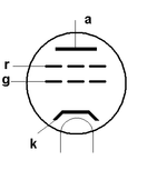
Vacuum tubes


Switches
-

Switch, Single Pole/Single Throw (SPST)
-

Switch, Single Pole/Double Throw (SPDT)
-

Switch, Double Pole/Double Throw (DPDT)
Circuit Breakers
-

Molded Case Circuit Breaker (MCCB)
Transformers
-

Transformer with center tap
-

Current Transformer
-

Zero-Sequence Current Transformer (ZSCT) (a.k.a. window-type current transformer)
-

Bushing-Type Current Transformer
-

Voltage Transformer
Miscellaneous
-

Single cell, multi-cell battery
-

Phone jacks


See also
References
External links
| Wikimedia Commons has media related to Electrical symbols. |
- International standard IEC 60617 DB Graphical symbols for diagrams
- Electrical Circuit's Schematic Symbols
- Circuit Symbols of Electronic Components
- Circuit Symbols for all Electronic Components
- List of Circuit Schematic Symbols
- Electrical & Electronic Drawing Symbols
- Collection of Electronic Symbols