Electrical resonance
Electrical resonance occurs in an electric circuit at a particular resonance frequency when the imaginary parts of impedances or admittances of circuit elements cancel each other. In some circuits this happens when the impedance between the input and output of the circuit is almost zero and the transfer function is close to one.
Resonant circuits exhibit ringing and can generate higher voltages and currents than are fed into them. They are widely used in wireless (radio) transmission for both transmission and reception.
LC circuits
Resonance of a circuit involving capacitors and inductors occurs because the collapsing magnetic field of the inductor generates an electric current in its windings that charges the capacitor, and then the discharging capacitor provides an electric current that builds the magnetic field in the inductor. This process is repeated continually. An analogy is a mechanical pendulum.
At resonance, the series impedance of the two elements is at a minimum and the parallel impedance is at maximum. Resonance is used for tuning and filtering, because it occurs at a particular frequency for given values of inductance and capacitance. It can be detrimental to the operation of communications circuits by causing unwanted sustained and transient oscillations that may cause noise, signal distortion, and damage to circuit elements.
Parallel resonance or near-to-resonance circuits can be used to prevent the waste of electrical energy, which would otherwise occur while the inductor built its field or the capacitor charged and discharged. As an example, asynchronous motors waste inductive current while synchronous ones waste capacitive current. The use of the two types in parallel makes the inductor feed the capacitor, and vice versa, maintaining the same resonant current in the circuit, and converting all the current into useful work.
Since the inductive reactance and the capacitive reactance are of equal magnitude, ωL = 1/ωC, so:

where ω = 2πf, in which f is the resonance frequency in hertz, L is the inductance in henries, and C is the capacitance in farads when standard SI units are used.
The quality of the resonance (how long it will ring when excited) is determined by its Q factor, which is a function of resistance. A true LC circuit would have infinite Q, but all real circuits have some resistance and smaller Q and are usually approximated more accurately by an RLC circuit.
RLC circuit

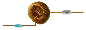
An RLC circuit (or LCR circuit) is an electrical circuit consisting of a resistor, an inductor, and a capacitor, connected in series or in parallel. The RLC part of the name is due to those letters being the usual electrical symbols for resistance, inductance and capacitance respectively. The circuit forms a harmonic oscillator for current and resonates similarly to an LC circuit. The main difference stemming from the presence of the resistor is that any oscillation induced in the circuit decays over time if it is not kept going by a source. This effect of the resistor is called damping. The presence of the resistance also reduces the peak resonant frequency. Some resistance is unavoidable in real circuits, even if a resistor is not specifically included as a component. A pure LC circuit is an ideal that only exists in theory.
There are many applications for this circuit. It is used in many different types of oscillator circuits. An important application is for tuning, such as in radio receivers or television sets, where they are used to select a narrow range of frequencies from the ambient radio waves. In this role the circuit is often referred to as a tuned circuit. An RLC circuit can be used as a band-pass filter, band-stop filter, low-pass filter or high-pass filter. The tuning application, for instance, is an example of band-pass filtering. The RLC filter is described as a second-order circuit, meaning that any voltage or current in the circuit can be described by a second-order differential equation in circuit analysis.
The three circuit elements can be combined in a number of different topologies. All three elements in series or all three elements in parallel are the simplest in concept and the most straightforward to analyse. There are, however, other arrangements, some with practical importance in real circuits. One issue often encountered is the need to take into account inductor resistance. Inductors are typically constructed from coils of wire, the resistance of which is not usually desirable, but it often has a significant effect on the circuit.
See also
- Antiresonance
- Antenna theory
- Cavity resonator
- Electronic oscillator
- Resonance
- Electronic filter
- Resonant energy transfer - wireless energy transmission between two resonant coils
References
![]() This article incorporates public domain material from the General Services Administration document "Federal Standard 1037C".
This article incorporates public domain material from the General Services Administration document "Federal Standard 1037C".