Dielectric barrier discharge
Dielectric-barrier discharge (DBD) is the electrical discharge between two electrodes separated by an insulating dielectric barrier. Originally called silent (inaudible) discharge and also known as ozone production discharge[1] or partial discharge,[2] it was first reported by Ernst Werner von Siemens in 1857.[3]

Process
The process normally uses high voltage alternating current, ranging from lower RF to microwave frequencies.[4] However, other methods were developed to extend the frequency range all the way down to the DC. One method was to use a high resistivity layer to cover one of the electrodes. This is known as the resistive barrier discharge.[5] Another technique using a semiconductor layer of gallium arsenide (GaAs) to replace the dielectric layer, enables these devices to be driven by a DC voltage between 580 V and 740 V.[6]
Construction
DBD devices can be made in many configurations, typically planar, using parallel plates separated by a dielectric or cylindrical, using coaxial plates with a dielectric tube between them.[7] In a common coaxial configuration, the dielectric is shaped in the same form as common fluorescent tubing. It is filled at atmospheric pressure with either a rare gas or rare gas-halide mix, with the glass walls acting as the dielectric barrier. Due to the atmospheric pressure level, such processes require high energy levels to sustain. Common dielectric materials include glass, quartz, ceramics and polymers. The gap distance between electrodes varies considerably, from less than 0.1 mm in plasma displays, several millimetres in ozone generators and up to several centimetres in CO2 lasers.
Operation
A multitude of random arcs form in operation gap exceeding 1.5 mm between the two electrodes during discharges in gases at the atmospheric pressure .[8] As the charges collect on the surface of the dielectric, they discharge in microseconds (millionths of a second), leading to their reformation elsewhere on the surface. Similar to other electrical discharge methods, the contained plasma is sustained if the continuous energy source provides the required degree of ionization, overcoming the recombination process leading to the extinction of the discharge plasma. Such recombinations are directly proportional to the collisions between the molecules and in turn to the pressure of the gas, as explained by Paschen's Law. The discharge process causes the emission of an energetic photon, the frequency and energy of which corresponds to the type of gas used to fill the discharge gap.
I-V characteristic of DBD

The electrical diagram of the DBD device at the absence of discharge can be presented in the form shown in Fig. 1 where  is capacitance of dielectric adjacent to one of two electrodes and
  is capacitance of the air (or gas) gap between the dielectric within the adjacent electrode footprint and the ground electrode.
  and
and  are capacity and resistance modeling electric response of plasma.
If a switch
are capacity and resistance modeling electric response of plasma.
If a switch  connects the capacitors and
  shown in Fig. 1 (there is no electrical breakdown), the voltage generator is connected to a circuit comprising two capacitors and connected in a series circuit. A capacitance of this circuit can be expressed as
 , (1)
, (1)
and the electric current  through this circuit can be expressed in the form
 , (2)
, (2)

where  is a generator voltage. Oscillograms and obtained in the case of the electrical breakdown of the operating gap, switch in Fig. 1 is connected to , are presented in Fig. 2.
We are going to describe, in a first order of approximation, the plasma response to voltage
is a generator voltage. Oscillograms and obtained in the case of the electrical breakdown of the operating gap, switch in Fig. 1 is connected to , are presented in Fig. 2.
We are going to describe, in a first order of approximation, the plasma response to voltage  applied to the gap in the same way as a series circuit of two invariable components and. To proof this assumption valuability, let us express the value in the form
 , (3)
, (3)
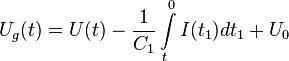
where the second term on the right hand side is a drop in potential on the capacitor , and  is the integration constant.
The current can be expressed in terms of the voltage and values and . For this purpose, let us present the value in the form of sum
is the integration constant.
The current can be expressed in terms of the voltage and values and . For this purpose, let us present the value in the form of sum
 , (4)
, (4)
where  and
and  represent the drops in potential on the resistor and capacitor respectively. Taking into account that the electric current through the circuit can be expressed as
  and consequently,
 ,
,
the equation (4) can be rewritten as the standard linear differential equation
 , (5)
, (5)
which solution is
 , (6)
, (6)
where  is the integration constant. Differentiating Equation (6) with respect to
  and substituting the result in Equation (5), one can express the current in terms of the voltage and values and :

![I(t)={\frac {1}{R_{p}}}\left[U_{g}(t)-{\frac {\exp(-t/R_{p}C_{p})}{R_{p}C_{p}}}\left(\int \limits _{{0}}^{{t}}U_{g}(t_{1})\exp(t_{1}/R_{p}C_{p})dt_{1}+C_{{int}}\right)\right]](/2014-wikipedia_en_all_02_2014/I/media/5/2/f/9/52f911a6d82f51105f893d7a59e6b868.png) , (7)
, (7)
where
 , (8)
, (8)
 is drop in potential on plasma, and
  is the constant near-electrode drop in potential. Four parameters: ,
  , , and can be found by procedure of fitting of the theoretical function , calculated from the experimental value by equation (7), with the actual electric current measured in experiment. Results of the least square fitting, corresponding to some particular case, are shown in Fig. 3. For detail of the equation (7) derivation and possibilities to analyse DBD parameters, see Ref.[9] The equation (7) represents the I-V characteristic of DBD in a most general form.
Applications
Usage of generated radiation
DBDs can be used to generate optical radiation by the relaxation of excited species in the plasma. The main application here is the generation of UV-radiation. Those excimer ultraviolet lamps can produce light with short wavelengths which can be used to produce ozone in industrial scales. Ozone is still used extensively in industrial air and water treatment.[7] Early 19th-century attempts at commercial nitric acid and ammonia production used DBDs[10] as several nitrogen-oxygen compounds are generated as discharge products.[3]
Usage of the generated plasma
The plasma itself is used to modify or clean (plasma cleaning) surfaces of materials (e.g. polymers, semiconductor surfaces), that can also act as dielectric barrier, or to modify gases <ref name=Shun'ko>M. E.V.Shun’ko and V.S.Belkin " Cleaning Properties of atomic oxygen excited to metastable state 2s22p4(1S0)", J. Appl. Phys 102, 083304 (2007)</ref> applied further to “soft” plasma cleaning and increasing adhesion of surfaces prepared for coating or gluing (flat panel display technologies).
Since the 19th century, DBDs were known for their decomposition of different gaseous compounds, such as NH3, H2S and CO2. Other modern applications include semiconductor manufacturing, germicidal processes, polymer surface treatment, high-power CO2 lasers typically used for welding and metal cutting, pollution control and plasma displays panels. The relatively lower temperature of DBDs makes it an attractive method of generating plasma at atmospheric pressure.
Medicine
Dielectric barrier discharges were used to generate relatively large volume diffuse plasmas at atmospheric pressure and applied to inactivate bacteria in the mid 1990s.[11] This eventually led to the development of a new field of applications, the biomedical applications of plasmas. This field is now known as plasma medicine.
Water treatment
An additional process when using chlorine gas for removal of bacteria and organic contaminates in drinking water supplies.[12] Treatment of public swimming baths, aquariums and fish ponds involves the use of ultraviolet radiation produced when a dielectric mixture of xenon gas and glass are used.[13][14]
Industry
A dielectric barrier discharge is one method of plasma treatment of textiles at atmospheric pressure and room temperature.[15] The treatment can be used to modify the surface properties of the textile to improve wettability, improve the absorption of dyes and adhesion, and for sterilization. DBD plasma provides a dry treatment that doesn't generate waste water or require drying of the fabric after treatment. For textile treatment, a DBD system requires a few kilovolts of alternating current, at between 1 and 100 kilohertz. Voltage is applied to insulated electrodes with a millimetre-size gap through which the textile passes.[16]
An excimer lamp can be used as a powerful source of short-wavelength ultraviolet light, useful in chemical processes such as surface cleaning of semiconductor wafers.[17] The lamp relies on a dielectric barrier discharge in an atmosphere of xenon and other gases to produce the excimers.
Properties
Due to their nature, these devices have the following properties:
- capacitive electric load: low Power Factor in range of 0.1 to 0.3
- high ignition voltage 1 - 10 kV
- huge amount of energy stored in electric field - requirement of energy recovery if DBD is not driven continuously
- voltages and currents during discharge event have major influence on discharge behaviour (filamented, homogeneous).
Operation with continuous sine waves or square waves is mostly used in high power industrial installations. Pulsed operation of DBDs may lead to higher discharge efficiencies.
Driving circuits
Drivers for this type of electric load are power HF-generators that in many cases contain a transformer for high voltage generation. They resemble the control gear used to operate compact fluorescent lamps or cold cathode fluorescent lamps. The operation mode and the topologies of circuits to operate [DBD] lamps with continuous sine or square waves are similar to those standard drivers. In these cases, the energy that is stored in the DBD's capacitance does not have to be recovered to the intermediate supply after each ignition. Instead, it stays within the circuit (oscillates between the [DBD]'s capacitance and at least one inductive component of the circuit) and only the real power, that is consumed by the lamp, has to be provided by the power supply. Differently, drivers for pulsed operation suffer from rather low power factor and in many cases must fully recover the DBD's energy. Since pulsed operation of [DBD] lamps can lead to increased lamp efficiency, international research led to suiting circuit concepts. Basic topologies are resonant flyback[18] and resonant half bridge.[19] A flexible circuit, that combines the two topologies is given in[20] and[21] and may be used to adaptively drive DBDs with varying capacitance.
An overview of different circuit concepts for the pulsed operation of DBD optical radiation sources is given in "Resonant Behaviour of Pulse Generators for the Efficient Drive of Optical Radiation Sources Based on Dielectric Barrier Discharges".[22]
References
- ↑ Matsuno, Hiromitsu, Nobuyuki Hishinuma, Kenichi Hirose, Kunio Kasagi, Fumitoshi Takemoto, Yoshinori Aiura, and TatsushiIgarashi. Dielectric barrier discharge lamp, United States Patent 5757132 (Commercial website). Freepatentsonline.com. First published 1998-05-26. Retrieved on 2007-08-05.
- ↑ Dhali, S.K. and I. Sardja. Dielectric-barrier discharge for the removal of SO2 fromflue gas. (Abstract only). IEEE International Conference on Plasma Science, 1989; IEEE Conference Record - Abstracts, 1989. Retrieved on 2007-08-05.
- ↑ 3.0 3.1 Kogelschatz, Ulrich, Baldur Eliasson, and Walter Egli. From ozone generators to flat television screens: history and future potential of dielectric-barrier discharges. Pure Applied Chemistry, Vol. 71, No. 10, pp. 1819-1828, 1999. Retrieved on 2007-08-05.
- ↑ "Aerosol charge distributions in Dielectric Barrier Discharges". Publication date 2009. European Aerosol Conference 2009 Karlsruhe. Retrieved 2010-12-10.
- ↑ M. Laroussi, I. Alexeff, J. P. Richardson, and F. F. Dyer " The Resistive Barrier Discharge", IEEE Trans. Plasma Sci. 30, 158 (2002)
- ↑ "Structure formation in a DC-driven "barrier" discharge stability analysis and numerical solutions". Publication date July 15–20, 2007. ICPIG Prague, Czech Republic. Retrieved 2010-12-09.
- ↑ 7.0 7.1 Kraus, Martin, Baldur Eliasson, Ulrich Kogelschatzb, and Alexander Wokauna. CO2 reforming of methane by the combination of dielectric-barrier discharges and catalysis Physical Chemistry Chemical Physics, 2001, 3, 294-300. Retrieved on 2007-08-05.
- ↑ "Dielectric-Barrier Discharges. Principle and Applications". ABB Corporate Research Ltd., Baden, Switzerland. 11 October 1997. Retrieved 19 January 2013.
- ↑ E.V.Shun’ko and V.S.Belkin " Treatment Surfaces with Atomic Oxygen Excited in Dielectric Barrier Discharge Plasma of O2 Admixed to N2)", AIP ADVANCES, 2, 022157-24 (2012)
- ↑ Nitrogen Classic Encyclopedia, Based on the 11th Edition of the Encyclopædia Britannica (pub. 1911), 1911encyclopedia.org.
- ↑ M. Laroussi, "Sterilization of contaminated matter with an atmospheric pressure plasma", IEEE Trans. Plasma Sci. 24, 1188 (1996)
- ↑ "Dielectric barrier discharge system with catalytically active porous segment for improvement of water treatmen". Department of Physics, University of West Bohemia, Univerzitni 22, 306 14 Plzen, Czech Republic 2008. Retrieved 9 January 2011.
- ↑ "UV v.s Chlorine". Atguv.com 2010. Retrieved 9 January 2011.
- ↑ "Dielectric barrier discharge lamp comprising an UV-B phosphor". Freepatentsonline.com 12/21/2010. Retrieved 9 January 2011.
- ↑ "Disinfection of materials". Retrieved 2010-12-16.
- ↑ The Textile Institute, Sustainable textiles, CRC Press, ISBN 978-1-84569-453-1 page 156
- ↑ "Dielectric". Siliconfareast.com 2001-2006. Retrieved 8 January 2011.
- ↑ "Current controlled driver for a Dielectric Barrier Discharge lamp". Publication date 21–24 June 2010. Power Electronics Conference (IPEC) 2010 International. Retrieved 2010-12-09.
- ↑ "Resonance behaviour of a pulsed electronic control gear for dielectric barrier discharges". Power Electronics, Machines and Drives (PEMD 2010), 5th IET International Conference on.
- ↑ "Patent application title: Device for Generation of Voltage Pulse Sequences In Particular for Operation of Capacitive Discharge Lamps". Publication date 2005. University of Karlsruhe. Retrieved 2011-05-23.
- ↑ "Patent application title: Adaptive Drive for Dielectric Barrier Discharge (DBD) Lamp". Publication date 2008. Briarcliff Manor, New York US. Retrieved 2010-12-09.
- ↑ "Resonant Behaviour of Pulse Generators for the Efficient Drive of Optical Radiation Sources Based on Dielectric Barrier Discharges". Publication date 10.07.2013. KIT sicentific publishing.