Cutaway drawing

| Part of a series on |
| Graphical projection |
|---|
 |
A cutaway drawing, also called a cutaway diagram is a 3D graphics, drawing, diagram and or illustration, in which surface elements a three-dimensional model are selectively removed, to make internal features visible, but without sacrificing the outer context entirely.
Overview
According to Diepstraten et al. (2003) "the purpose of a cutaway drawing is to allow the viewer to have a look into an otherwise solid opaque object. Instead of letting the inner object shine through the surrounding surface, parts of outside object are simply removed. This produces a visual appearance as if someone had cutout a piece of the object or sliced it into parts. Cutaway illustrations avoid ambiguities with respect to spatial ordering, provide a sharp contrast between foreground and background objects, and facilitate a good understanding of spatial ordering".[1]
Though cutaway drawing are not dimensioned manufacturing blueprints, they are meticulously drawn by a handful of devoted artists who either had access to manufacturing details or deduced them by observing the visible evidence of the hidden skeleton (e.g. rivet lines, etc.). The goal of this drawings in studies can be to identify common design patterns for particular vehicle classes. Thus, the accuracy of most of these drawings, while not 100 percent, is certainly high enough for this purpose.[2]
The technique is used extensively in computer-aided design, see first image. It has also been incorporated into the user interface of some video games. In The Sims, for instance, users can select through a control panel whether to view the house they are building with no walls, cutaway walls, or full walls.[3]
History

The cutaway view and the exploded view were minor graphic inventions of the Renaissance that also clarified pictorial representation. This cutaway view originates in the early fifteenth century notebooks of Marino Taccola (1382 – 1453). In the 16th century cutaway views in definite form were used in Georgius Agricola's (1494-1555) mining book De Re Metallica to illustrate underground operations. [4] The 1556 book is a complete and systematic treatise on mining and extractive metallurgy, illustrated with many fine and interesting woodcuts which illustrate every conceivable process to extract ores from the ground and metal from the ore, and more besides. It shows the many watermills used in mining, such as the machine for lifting men and material into and out of a mine shaft, see image.
The term "Cutaway drawing" was already in use in the 19th century but, became popular in the 1930s.
Technique
The location and shape to cut the outside object depends on many different factors, for example:[1]
- the sizes and shapes of the inside and outside objects,
- the semantics of the objects,
- personal taste, etc.
These factors, according to Diepstraten et al. (2003), "can seldom be formalized in a simple algorithm, But the properties of cutaway can be distinguish in two classes of cutaways of a drawing":[1]
- cutout : illustrations were the cutaway is retricted to very simple and regularly shaped of often only a small number of planar slices into the outside object.
- breakaway : a cutaway realized by a single hole in the outside of the object.
Examples
Some more examples of cutaway drawings, from products and systems to architectural building.
-

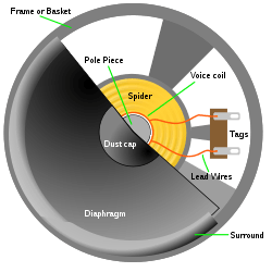
A dynamic loudspeaker
-

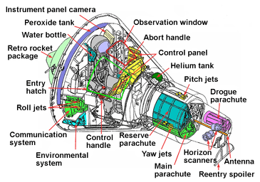
Mercury spacecraft.
-

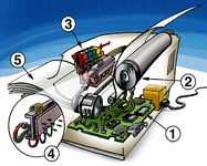
Cutaway of an inkjet printer
-

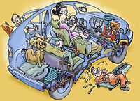
Cutaway of a hybrid car
See also
Similar types of technical drawings
References
- ↑ 1.0 1.1 1.2 J. Diepstraten, D. Weiskopf & T. Ertl (2003). "Interactive Cutaway Illustrations". in: Eurographics 2003. P. Brunet and D. Fellner (ed). Vol 22 (2003), Nr 3.
- ↑ Mark D. Sensmeier, and Jamshid A. Samareh (2003). "A Study of Vehicle Structural Layouts in Post-WWII Aircraft" Paper American Institute of Aeronautics and Astronautics.
- ↑ "The Sims Control Panel".
- ↑ Eugene S. Ferguson (1999). Engineering and the Mind's Eye. p.82.
External links
| Wikimedia Commons has media related to Cutaway diagrams. |

