Crowbar (circuit)

A crowbar circuit is an electrical circuit used to prevent an overvoltage condition of a power supply unit from damaging the circuits attached to the power supply. It operates by putting a short circuit or low resistance path across the voltage source, much as if one dropped a tool of the same name across the output terminals of the power supply. Crowbar circuits are frequently implemented using a thyristor, TRIAC, trisil or thyratron as the shorting device. Once triggered, they depend on the current-limiting circuitry of the power supply or, if that fails, the blowing of the line fuse or tripping the circuit breaker.
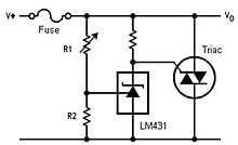
The theory of operation of the crowbar circuit lies with the voltage division provided by r1 and r2 and the cascading effect onto the LM 431 (configured as a voltage regulator) and subsequently the Triac. Observing KVL, the sum of the Voltages of the dividing resistors must equal to the sum of the voltages of the resistor in series with the voltage regulator that is essentially a Zener diode. As the Zener diode can be modeled as a constant voltage source (if operating in the active region), the resistor in series with it will drop the difference of the supply voltage and that of the Zener. As the base of the Triac is tied into this node, the current flowing into the base 'ic' is the voltage drop of the resistor divided by the resistance value. Dependent upon the gain factor beta 'β' of the Triac, the current flowing between the supply Voltages via the Triac (known as the collector current 'ie' or the very similarity value emitter current 'ie') is the base current times beta.
When an over voltage occurs, the voltage drop of r1 exceeds the equally valued r2 and Zener diode, resulting in a higher Triac base current, that causes via gain, a higher current to flow though the Triac and therefore, either tripping an upstream circuit breaker or blowing a fuse.
A crowbar circuit is distinct from a clamp in that, once triggered, it pulls the voltage below the trigger level, usually close to ground. A clamp prevents the voltage from exceeding a preset level. Thus, a crowbar will not automatically return to normal operation when the overvoltage condition is removed; power must be removed entirely to stop its conduction.
An active crowbar is a crowbar that can remove the short circuit when the transient is over thus allowing the device to resume normal operation. Active crowbars use a transistor, gate turn off (GTO) thyristor or forced commutated thyristor instead of a thyristor to short the circuit. Active crowbars are commonly used to protect the frequency converter in the rotor circuit of doubly fed generators against high voltage and current transients caused by the voltage dips in the power network. Thus the generator can ride through the fault and quickly continue the operation even during the voltage dip.
The advantage of a crowbar over a clamp is that the low holding voltage of the crowbar lets it carry higher fault current without dissipating much power (which could otherwise cause overheating). Also, a crowbar is more likely than a clamp to deactivate a device (by blowing a fuse or tripping a breaker), bringing attention to the faulty equipment.
The term is also used as a verb to describe the act of short-circuiting the output of a power supply.
Applications
High voltage crowbars are used for HV tube (Klystron and IOT) protection.
Many bench top power supplies have a crowbar circuit to protect the connected equipment.
References
- Paul Horowitz and Winfield Hill, The Art of Electronics, Second Edition, pages 318-319, Cambridge University Press, 1989.
- Article about design of thyristor-based crowbar circuits
- IPP Garching 80kA Crowbar from ' ABB Pulse Power