Wireless power
Wireless power or wireless energy transmission is the transmission of electrical energy from a power source to an electrical load without man-made conductors. Wireless transmission is useful in cases where interconnecting wires are inconvenient, hazardous, or impossible. The problem of wireless power transmission differs from that of wireless telecommunications, such as radio. In the latter, the proportion of energy received becomes critical only if it is too low for the signal to be distinguished from the background noise.[4] With wireless power, efficiency is the more significant parameter. A large part of the energy sent out by the generating plant must arrive at the receiver or receivers to make the system economical.
The most common form of wireless power transmission is carried out using direct induction followed by resonant magnetic induction. Other methods under consideration are electromagnetic radiation in the form of microwaves or lasers[5] and electrical conduction through natural media.[6]
Electric energy transfer
An electric current flowing through a conductor, such as a wire, carries electrical energy. When an electric current passes through a circuit there is an electric field in the dielectric surrounding the conductor; magnetic field lines around the conductor and lines of electric force radially about the conductor.[7]
In a direct current circuit, if the current is continuous, the fields are constant; there is a condition of stress in the space surrounding the conductor, which represents stored electric and magnetic energy, just as a compressed spring or a moving mass represents stored energy. In an alternating current circuit, the fields also alternate; that is, with every half wave of current and of voltage, the magnetic and the electric field start at the conductor and run outwards into space with the speed of light.[8] Where these alternating fields impinge on another conductor a voltage and a current are induced.[7]
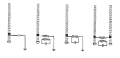
Any change in the electrical conditions of the circuit, whether internal[9] or external[10] involves a readjustment of the stored magnetic and electric field energy of the circuit, that is, a so-called transient. A transient is of the general character of a condenser discharge through an inductive circuit. The phenomenon of the condenser discharge through an inductive circuit therefore is of the greatest importance to the engineer, as the foremost cause of high-voltage and high-frequency troubles in electric circuits.[11]
Electromagnetic induction is proportional to the intensity of the current and voltage in the conductor which produces the fields and to the frequency. The higher the frequency the more intense the inductive effect. Energy is transferred from a conductor that produces the fields (the primary) to any conductor on which the fields impinge (the secondary). Part of the energy of the primary conductor passes inductively across space into secondary conductor and the energy decreases rapidly along the primary conductor. A high frequency current does not pass for long distances along a conductor but rapidly transfers its energy by induction to adjacent conductors. Higher induction resulting from the higher frequency is the explanation of the apparent difference in the propagation of high frequency disturbances from the propagation of the low frequency power of alternating current systems. The higher the frequency the more preponderant become the inductive effects that transfer energy from circuit to circuit across space. The more rapidly the energy decreases and the current dies out along the circuit, the more local is the phenomenon.[7]
The flow of electric energy thus comprises phenomena inside the conductor[12] and phenomena in the space outside the conductor—the electric field—which, in a continuous current circuit, is a condition of steady magnetic and dielectric stress, and in an alternating current circuit is alternating, that is, an electric wave launched by the conductor[7] to become far-field electromagnetic radiation traveling through space with the speed of light.
In electric power transmission and distribution, the phenomena inside the conductor are of main importance, and the electric field of the conductor is usually observed only incidentally.[13] Inversely, in the use of electric power for radio telecommunications it is only the electric and magnetic fields outside of the conductor, that is far-field electromagnetic radiation, which is of importance in transmitting the message. The phenomenon in the conductor, the current in the launching structure, is not used.[7]
The electric charge displacement in the conductor produces a magnetic field and resultant lines of electric force. The magnetic field is a maximum in the direction concentric, or approximately so, to the conductor. That is, a ferromagnetic body[14] tends to set itself in a direction at right angles to the conductor. The electric field has a maximum in a direction radial, or approximately so, to the conductor. The electric field component tends in a direction radial to the conductor and dielectric bodies may be attracted or repelled radially to the conductor.[15]
The electric field of a circuit over which energy flows has three main axes at right angles with each other:
- The magnetic field, concentric with the conductor.
- The lines of electric force, radial to the conductor.
- The power gradient, parallel to the conductor.
Where the electric circuit consists of several conductors, the electric fields of the conductors superimpose upon each other, and the resultant magnetic field lines and lines of electric force are not concentric and radial respectively, except approximately in the immediate neighborhood of the conductor. Between parallel conductors they are conjugate of circles. Neither the power consumption in the conductor, nor the magnetic field, nor the electric field, are proportional to the flow of energy through the circuit. However, the product of the intensity of the magnetic field and the intensity of the electric field is proportional to the flow of energy or the power, and the power is therefore resolved into a product of the two components i and e, which are chosen proportional respectively to the intensity of the magnetic field and of the electric field. The component called the current is defined as that factor of the electric power which is proportional to the magnetic field, and the other component, called the voltage, is defined as that factor of the electric power which is proportional to the electric field.[15]
In radio telecommunications the electric field of the transmit antenna propagates through space as a radio wave and impinges upon the receive antenna where it is observed by its magnetic and electric effect.[15] Radio waves, microwaves, infrared radiation, visible light, ultraviolet radiation, X rays and gamma rays are shown to be the same electromagnetic radiation phenomenon, differing one from the other only in frequency of vibration.[7][16]
Electromagnetic induction
Energy transfer by electromagnetic induction is typically magnetic but capacitive coupling can also be achieved.
Electrodynamic induction method
The electrodynamic induction wireless transmission technique is near field over distances up to about one-sixth of the wavelength used. Near field energy itself is non-radiative but some radiative losses do occur. In addition there are usually resistive losses. With electrodynamic induction, electric current flowing through a primary coil creates a magnetic field that acts on a secondary coil producing a current within it. Coupling must be tight in order to achieve high efficiency. As the distance from the primary is increased, more and more of the magnetic field misses the secondary. Even over a relatively short range the inductive coupling is grossly inefficient, wasting much of the transmitted energy.[17]
This action of an electrical transformer is the simplest form of wireless power transmission. The primary and secondary circuits of a transformer are not directly connected. Energy transfer takes place through a process known as mutual induction. Principal functions are stepping the primary voltage either up or down and electrical isolation. Mobile phone and electric toothbrush battery chargers, and electrical power distribution transformers are examples of how this principle is used. Induction cookers use this method. The main drawback to this basic form of wireless transmission is short range. The receiver must be directly adjacent to the transmitter or induction unit in order to efficiently couple with it.

The application of resonance increases the transmission range somewhat. When resonant coupling is used, the transmitter and receiver inductors are tuned to the same natural frequency. Performance can be further improved by modifying the drive current from a sinusoidal to a nonsinusoidal transient waveform.[18] In this way significant power may be transmitted between two mutually-attuned LC circuits having a relatively low coefficient of coupling. Transmitting and receiving coils are usually single layer solenoids or flat spirals with parallel capacitors, which, in combination, allow the receiving element to be tuned to the transmitter frequency.
Common uses of resonance-enhanced electrodynamic induction are charging the batteries of portable devices such as laptop computers and cell phones, medical implants and electric vehicles.[19][20][21] A localized charging technique[22] selects the appropriate transmitting coil in a multilayer winding array structure.[23] Resonance is used in both the wireless charging pad (the transmitter circuit) and the receiver module (embedded in the load) to maximize energy transfer efficiency. This approach is suitable for universal wireless charging pads for portable electronics such as mobile phones. It has been adopted as part of the Qi wireless charging standard.
It is also used for powering devices having no batteries, such as RFID patches and contactless smartcards, and to couple electrical energy from the primary inductor to the helical resonator of Tesla coil wireless power transmitters.
Electrostatic induction method

Electrostatic induction or capacitive coupling is the passage of electrical energy through a dielectric. In practice it is an electric field gradient or differential capacitance between two or more insulated terminals, plates, electrodes, or nodes that are elevated over a conducting ground plane. The electric field is created by charging the plates with a high potential, high frequency alternating current power supply. The capacitance between two elevated terminals and a powered device form a voltage divider.
The electric energy transmitted by means of electrostatic induction can be utilized by a receiving device, such as a wireless lamp.[24][25][26] Nikola Tesla demonstrated the illumination of wireless lamps by energy that was coupled to them through an alternating electric field.[1][27][28]
"Instead of depending on electrodynamic induction at a distance to light the tube . . . [the] ideal way of lighting a hall or room would . . . be to produce such a condition in it that an illuminating device could be moved and put anywhere, and that it is lighted, no matter where it is put and without being electrically connected to anything. I have been able to produce such a condition by creating in the room a powerful, rapidly alternating electrostatic field. For this purpose I suspend a sheet of metal a distance from the ceiling on insulating cords and connect it to one terminal of the induction coil, the other terminal being preferably connected to the ground. Or else I suspend two sheets . . . each sheet being connected with one of the terminals of the coil, and their size being carefully determined. An exhausted tube may then be carried in the hand anywhere between the sheets or placed anywhere, even a certain distance beyond them; it remains always luminous."[29]
The principle of electrostatic induction is applicable to the electrical conduction wireless transmission method.
“In some cases when small amounts of energy are required the high elevation of the terminals, and more particularly of the receiving-terminal D', may not be necessary, since, especially when the frequency of the currents is very high, a sufficient amount of energy may be collected at that terminal by electrostatic induction from the upper air strata, which are rendered conducting by the active terminal of the transmitter or through which the currents from the same are conveyed."[30]
Electromagnetic radiation
Far field methods achieve longer ranges, often multiple kilometer ranges, where the distance is much greater than the diameter of the device(s). The main reason for longer ranges with radio wave and optical devices is the fact that electromagnetic radiation in the far-field can be made to match the shape of the receiving area (using high directivity antennas or well-collimated laser beam) thereby delivering almost all emitted power at long ranges. The maximum directivity for antennas is physically limited by diffraction.
Beamed power, size, distance, and efficiency
The dimensions of the components may be dictated by the distance from transmitter to receiver, the wavelength and the Rayleigh criterion or diffraction limit, used in standard radio frequency antenna design, which also applies to lasers. In addition to the Rayleigh criterion Airy's diffraction limit is also frequently used to determine an approximate spot size at an arbitrary distance from the aperture.
The Rayleigh criterion dictates that any radio wave, microwave or laser beam will spread and become weaker and diffuse over distance; the larger the transmitter antenna or laser aperture compared to the wavelength of radiation, the tighter the beam and the less it will spread as a function of distance (and vice versa). Smaller antennae also suffer from excessive losses due to side lobes. However, the concept of laser aperture considerably differs from an antenna. Typically, a laser aperture much larger than the wavelength induces multi-moded radiation and mostly collimators are used before emitted radiation couples into a fiber or into space.
Ultimately, beamwidth is physically determined by diffraction due to the dish size in relation to the wavelength of the electromagnetic radiation used to make the beam. Microwave power beaming can be more efficient than lasers, and is less prone to atmospheric attenuation caused by dust or water vapor losing atmosphere to vaporize the water in contact.
Then the power levels are calculated by combining the above parameters together, and adding in the gains and losses due to the antenna characteristics and the transparency and dispersion of the medium through which the radiation passes. That process is known as calculating a link budget.
Microwave method
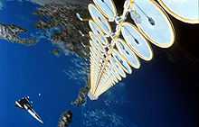
Power transmission via radio waves can be made more directional, allowing longer distance power beaming, with shorter wavelengths of electromagnetic radiation, typically in the microwave range. A rectenna may be used to convert the microwave energy back into electricity. Rectenna conversion efficiencies exceeding 95% have been realized. Power beaming using microwaves has been proposed for the transmission of energy from orbiting solar power satellites to Earth and the beaming of power to spacecraft leaving orbit has been considered.[5][31]
Power beaming by microwaves has the difficulty that for most space applications the required aperture sizes are very large due to diffraction limiting antenna directionality. For example, the 1978 NASA Study of solar power satellites required a 1-km diameter transmitting antenna, and a 10 km diameter receiving rectenna, for a microwave beam at 2.45 GHz.[32] These sizes can be somewhat decreased by using shorter wavelengths, although short wavelengths may have difficulties with atmospheric absorption and beam blockage by rain or water droplets. Because of the "thinned array curse," it is not possible to make a narrower beam by combining the beams of several smaller satellites.
For earthbound applications a large area 10 km diameter receiving array allows large total power levels to be used while operating at the low power density suggested for human electromagnetic exposure safety. A human safe power density of 1 mW/cm2 distributed across a 10 km diameter area corresponds to 750 megawatts total power level. This is the power level found in many modern electric power plants.
Following World War II, which saw the development of high-power microwave emitters known as cavity magnetrons, the idea of using microwaves to transmit power was researched. By 1964, a miniature helicopter propelled by microwave power had been demonstrated.[33]
Japanese researcher Hidetsugu Yagi also investigated wireless energy transmission using a directional array antenna that he designed. In February 1926, Yagi and Uda published their first paper on the tuned high-gain directional array now known as the Yagi antenna. While it did not prove to be particularly useful for power transmission, this beam antenna has been widely adopted throughout the broadcasting and wireless telecommunications industries due to its excellent performance characteristics.[34]
Wireless high power transmission using microwaves is well proven. Experiments in the tens of kilowatts have been performed at Goldstone in California in 1975[35][36][37] and more recently (1997) at Grand Bassin on Reunion Island.[38] These methods achieve distances on the order of a kilometer.
It should also be mentioned that microwave conversion efficiency under experimental conditions was measured to be around 54% efficient.[39]
Laser method
In the case of electromagnetic radiation closer to the visible region of the spectrum (tens of micrometers to tens of nanometres), power can be transmitted by converting electricity into a laser beam that is then pointed at a photovoltaic cell.[40] This mechanism is generally known as "power beaming" because the power is beamed at a receiver that can convert it to electrical energy.
Compared to other wireless methods:[41]
- Collimated monochromatic wavefront propagation allows narrow beam cross-section area for transmission over large distances.
- Compact size: solid state lasers fit into small products.
- No radio-frequency interference to existing radio communication such as Wi-Fi and cell phones.
- Access control: only receivers hit by the laser receive power.
Drawbacks include:
- Laser radiation is hazardous. Low power levels can blind humans and other animals. High power levels can kill through localized spot heating.
- Conversion between electricity and light is inefficient. Photovoltaic cells achieve only 40%–50% efficiency.[42] (Efficiency is higher with monochromatic light than with solar panels).
- Atmospheric absorption, and absorption and scattering by clouds, fog, rain, etc., causes up to 100% losses.
- Requires a direct line of sight with the target.
Laser "powerbeaming" technology has been mostly explored in military weapons[43][44][45] and aerospace[46][47] applications and is now being developed for commercial and consumer electronics. Wireless energy transfer systems using lasers for consumer space have to satisfy laser safety requirements standardized under IEC 60825.[citation needed]
Other details include propagation,[48] and the Coherence and the range limitation problem.[49]
Geoffrey Landis[50][51][52] is one of the pioneers of solar power satellites[53] and laser-based transfer of energy especially for space and lunar missions. The demand for safe and frequent space missions has resulted in proposals for a laser-powered space elevator.[54][55]
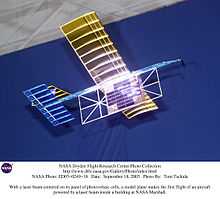
NASA's Dryden Flight Research Center demonstrated a lightweight unmanned model plane powered by a laser beam.[56] This proof-of-concept demonstrates the feasibility of periodic recharging using the laser beam system.
Electrical conduction

U.S. Patent 1,119,732
Disturbed charge of ground and air method
The wireless transmission of alternating current electricity through the earth with an equivalent electrical displacement through the air above it achieves long ranges that are superior to the resonant electrical induction methods and favorably comparable to the electromagnetic radiation methods.[57] Electrical energy can be transmitted through inhomogeneous Earth with low loss because the net resistance between earth antipodes is less than 1 ohm.[6] The electrical displacement takes place predominantly by electrical conduction through the oceans, and metallic ore bodies and similar subsurface structures. The electrical displacement is also by means of electrostatic induction through the more dielectric regions such as quartz deposits and other non-conducting minerals.[58][59] Receivers are energized by currents through the earth while an equivalent electric displacement occurs in the atmosphere.[60]
This energy transfer technique is suitable for transmission of electrical power in industrial quantities and also for wireless broadband telecommunications. The Wardenclyffe Tower project was an early commercial venture for trans-Atlantic wireless telephony and proof-of-concept demonstrations of global wireless power transmission using this method.[61] The facility was not completed due to insufficient funding.[62]
Terrestrial transmission line with atmospheric return
Single wire with Earth return electrical power transmission systems rely on current flowing through the earth plus a single wire insulated from the earth to complete the circuit. In emergencies high-voltage direct current power transmission systems can also operate in the 'single wire with earth return' mode. Elimination of the raised insulated wire, and transmission of high-potential alternating current through the earth with an atmospheric return circuit is the basis of this method of wireless electrical power transmission.
The atmospheric conduction method depends upon the passage of electrical current through the earth, and through the upper troposphere and the stratosphere.[63] Current flow is induced by electrostatic induction up to an elevation of approximately 3 miles (4.8 km) above Earth's surface.[64][65] Electrical conduction and the flow of current through the upper atmospheric strata starting at a barometric pressure of approximately 130 millimeters of mercury is made possible by the creation of capacitively coupled discharge plasma through the process of atmospheric ionization.[66][67][68] In this way electric lamps can be lit and electric motors turned at moderate distances. The transmitted energy can be detected at much greater distances.[69]
A global system for "the transmission of electrical energy without wires" called the World Wireless System, dependent upon the high electrical conductivity of plasma and the high electrical conductivity of the earth, was proposed as early as 1904.[70][71]
Terrestrial single-conductor surface wave transmission line
The fundamental earth resonance frequency is approximately 11.78 Hz.[74] A higher harmonic of this fundamental frequency is used.[75]
"The frequency should be smaller than twenty thousand per second, though shorter waves might be practicable"[76][77][78][79]
Observations have been made that may be inconsistent with a basic tenet of physics related to the scalar derivatives of the electromagnetic potentials[80][81][82][83][84][85][86] that are presently considered to be nonphysical.[87]
Timeline of wireless power
- 1826: André-Marie Ampère develops Ampère's circuital law showing that electric current produces a magnetic field.[88]
- 1831: Michael Faraday develops Faraday's law of induction describing the electromagnetic force induced in a conductor by a time-varying magnetic flux.
- 1836: Nicholas Callan invents the electrical transformer, also known as the induction coil.
- 1865: James Clerk Maxwell synthesizes the previous observations, experiments and equations of electricity, magnetism and optics into a consistent theory and mathematically models the behavior of electromagnetic radiation in a set of partial differential equations known as Maxwell's equations.
- 1888: Heinrich Rudolf Hertz confirms the existence of electromagnetic radiation. Hertz’s "apparatus for generating electromagnetic waves" was a VHF or UHF "radio wave" spark gap transmitter.
- 1891: Tesla demonstrates wireless energy transmission by means of electrostatic induction using a high-tension induction coil before the American Institute of Electrical Engineers at Columbia College.[89]
- 1893: Tesla demonstrates the wireless illumination of phosphorescent lamps of his design at the World's Columbian Exposition in Chicago.[90]
- 1893: Tesla publicly demonstrates wireless power and proposes the wireless transmission of signals before a meeting of the National Electric Light Association in St. Louis.[26][91][92][93]
- 1894: Tesla lights incandescent lamps wirelessly at the 35 South Fifth Avenue laboratory in New York City by means of "electro-dynamic induction" or resonant inductive coupling.[94][95][96]
- 1894: Hutin & LeBlanc, espouse long held view that inductive energy transfer should be possible, they received U.S. Patent 527,857 describing a system for power transmission at 3 kHz.[97]
- 1894: Jagdish Chandra Bose rings a bell at a distance using electromagnetic waves and also ignites gunpowder, showing that communications signals can be sent without using wires.[98][99]
- 1895: Marconi demonstrates radio transmission over a distance of 1.5 miles.[93][100] Developed Marconi's Law.
- 1896: Tesla demonstrates wireless transmission over a distance of about 48 kilometres (30 mi).[101]
- 1897: Tesla files his first patent application dealing specifically with wireless transmission.
- 1899: Tesla continues wireless power transmission research in Colorado Springs and writes, "the inferiority of the induction method would appear immense as compared with the disturbed charge of ground and air method."[102]
- 1902: Nikola Tesla vs. Reginald Fessenden – U.S. Patent Interference No. 21,701, System of Signaling (wireless); wireless power transmission, time and frequency domain spread spectrum telecommunications, electronic logic gates in general.[103]
- 1904: At the St. Louis World's Fair, a prize is offered for a successful attempt to drive a 0.1 horsepower (75 W) airship motor by energy transmitted through space at a distance of at least 100 feet (30 m).[104]
- 1916: Tesla states, "In my [disturbed charge of ground and air] system, you should free yourself of the idea that there is [electromagnetic] radiation, that energy is radiated. It is not radiated; it is conserved."[105]
- 1917: The Wardenclyffe tower is demolished.
- 1926: Shintaro Uda and Hidetsugu Yagi publish their first paper on Uda's "tuned high-gain directional array"[34] better known as the Yagi antenna.
- 1961: William C. Brown publishes an article exploring possibilities of microwave power transmission.[106][107]
- 1968: Peter Glaser proposes wirelessly transmitting solar energy captured in space using "Powerbeaming" technology.[108][109] This is usually recognized as the first description of a solar power satellite.
- 1973: The world's first passive RFID system is demonstrated at Los-Alamos National Lab.[110]
- 1975: Goldstone Deep Space Communications Complex does experiments in the tens of kilowatts.[35][36][37]
- 1998: RFID tags are powered by electrodynamic induction over a few feet.[citation needed]
- 1999: Prof. Shu Yuen (Ron) Hui and Mr. S.C. Tang file a patent on "Coreless Printed-Circuit-Board (PCB) transformers and operating techniques", which form the basis for future planar charging surface with "vertical flux" leaving the planar surface. The circuit uses resonant circuits for wireless power transfer. EP(GB)0935263B
- 2000: Prof. Shu Yuen (Ron) Hui invent a planar wireless charging pad using the "vertical flux" approach and resonant power transfer for charging portable consumer electronic products. A patent is filed on "Apparatus and method of an inductive battery charger,” PCT Patent PCT/AU03/00 721, 2000.
- 2001 Prof. Shu Yuen (Ron) Hui and Dr. S.C. Tang file a patent on "Planar Printed-Circuit-Board Transformers with Effective Electromagnetic Interference (EMI) Shielding". The EM shield consists of a thin layer of ferrite and a thin layer of copper sheet. It enables the underneath of the future wireless charging pads to be shielded with a thin EM shield structure with thickness of typically 0.7mm or less. U.S. Patent 6,501,364.
- 2001: Prof. Ron Hui's team demonstrate that the coreless PCB transformer can transmit power close to 100W in ‘A low-profile low-power converter with coreless PCB isolation transformer, IEEE Transactions on Power Electronics, Volume: 16 Issue: 3 , May 2001. A team of Philips Research Center Aachen, led by Dr. Eberhard Waffenschmidt, use it to power an 100W lighting device in their paper "Size advantage of coreless transformers in the MHz range" in the European Power Electronics Conference in Graz.
- 2002: Prof. Shu Yuen (Ron) Hui extends the planar wireless charging pad concept using the vertical flux approach to incorporate free-positioning feature for multiple loads. This is achieved by using a multilayer planar winding array structure. Patent were granted as "Planar Inductive Battery Charger", GB2389720 and GB 2389767.[citation needed]
- 2005: Prof. Shu Yuen (Ron) Hui and Dr. W.C. Ho publish their work in the IEEE Transactions on a planar wireless charging platform with free-positioning feature. The planar wireless charging pad is able to charge several loads simultaneously on a flat surface.[citation needed]
- 2007: A localized charging technique is reported by Dr. Xun Liu and Prof. Ron Hui for the wireless charging pad with free-positioning feature. With the aid of the double-layer EM shields enclosing the transmitter and receiver coils, the localized charging selects the right transmitter coil so as to minimize flux leakage and human exposure to radiation.[citation needed]
- 2007: Using electrodynamic induction the WiTricity physics research group, led by Prof. Marin Soljacic at MIT, wirelessly power a 60W light bulb with 40% efficiency at a 2 metres (6.6 ft) distance with two 60 cm-diameter coils.[111]
- 2008: Bombardier offers a new wireless power transmission product PRIMOVE, a system for use on trams and light-rail vehicles.[112]
- 2008: Intel reproduces the original 1894 implementation of electrodynamic induction and Prof. John Boys group's 1988 follow-up experiments by wirelessly powering a nearby light bulb with 75% efficiency.[113]
- 2008: Greg Leyh and Mike Kennan of the Nevada Lightning Laboratory publish a paper on the disturbed charge of ground and air method of wireless power transmission with circuit simulations and test results showing an efficiency greater than can be obtained using the electrodynamic induction method.[57]
- 2009: Powermat Technologies introduced wireless charging systems, that work with a combination of radio-frequency identification (RFID) and electromagnetic induction[114]
- 2009: Palm (now a division of HP) launches the Palm Pre smartphone with the Palm Touchstone wireless charger.
- 2009: A Consortium of interested companies called the Wireless Power Consortium announce they are nearing completion for a new industry standard for low-power (which is eventually published in August 2010) inductive charging.[115]
- 2009: An Ex approved Torch and Charger aimed at the offshore market is introduced.[116] This product is developed by Wireless Power & Communication, a Norway based company.
- 2009: A simple analytical electrical model of electrodynamic induction power transmission is proposed and applied to a wireless power transfer system for implantable devices.[117]
- 2009: Lasermotive uses diode laser to win $900k NASA prize in power beaming, breaking several world records in power and distance, by transmitting over a kilowatt more than several hundred meters.[118]
- 2009: Sony shows a wireless electrodynamic-induction powered TV set, 60 W over 50 cm[119]
- 2010: Haier Group debuts “the world's first” completely wireless LCD television at CES 2010 based on Prof. Marin Soljacic's follow-up research on the 1894 electrodynamic induction wireless energy transmission method and the Wireless Home Digital Interface (WHDI).[120]
- 2010: System On Chip (SoC) group in University of British Columbia develops a highly efficient wireless power transmission systems using 4-coils. The design is optimized for implantable applications and power transfer efficiency of 82% is achieved.[121]
- 2012: A group at University of Toronto, presented for the first time a closed form analytical solution for the optimum load that achieves the maximum possible wireless power transfer efficiency under arbitrary input impedance conditions based on the general two-port parameters of the network. The proposed method effectively decoupled the design of the inductive coupling two-port from the problem of loading and power amplifier design.[122]
- 2012: "Bioelectromagnetics and Implantable Devices" group in University of Utah, USA develops an efficient resonance based wireless power and data transfer system for biomedical Implants. Presented design achieves more than twice the efficiency and frequency bandwidth compared to conventional inductive link approach. Design approach is extendable to other industrial "smart" wireless power transfer system.[123]
- 2012: Christopher Tucker, Kevin Warwick and William Holderbaum of the University of Reading, UK develop a highly efficient, compact power transfer system safe for use in human proximity. The design is simple and uses only a few components to generate stable currents for biomedical implants. It resulted from research that directly attempted to extend Tesla’s 1897 wireless power work.[124]
- 2013: Resonance based multi-coil wireless power transfer system is proposed to reduce the variation in power transfer efficiency and data bandwidth with coupling variation. Such systems can compensate the effect of coil misalignment on system performance.[125][126]
- 2013: A fully integrated wireless power receiver is demonstrated in CMOS process by a group at University of Toronto. The designed prototype requires no off-chip components or post-processing steps. The demonstrated single-chip prototype is only a few millimeters on each side, mass producible and heavily reduces the cost. This level of integration also enables new possibilities for disposable lab-on-chip solutions.[127]
- 2013: The concept of a virtual waveguide controlled by ordered magnetic fields for wireless power transmission is proposed.[128]
- 2014: The first microfluidic implant coil is proposed for the wireless power transfer to the flexible telemetry system. The work demonstrates a soft and flexible coil fabricated with a liquid metal alloy encased in a biocompatible elastomeric substrate to target the application of biomedical implantable devices. [129]
See also
- Beam-powered propulsion
- Beam Power Challenge – one of the NASA Centennial Challenges
- Differential capacitance
- Distributed generation
- Electricity distribution
- Electric power transmission
- Electromagnetic compatibility
- Electromagnetic radiation and health
- Energy harvesting
- Fermi gas
- Free electron model
- Friis transmission equation
- Microwave power transmission
- Resonant inductive coupling
- Surface plasmon
- Thinned array curse
- Transmission medium
- Wardenclyffe Tower
Further reading
- Books
- Walker, J., Halliday, D., & Resnick, R. (2011). Fundamentals of physics. Hoboken, NJ: Wiley.
- Hu, A. P. (2009). Wireless/Contactless power supply: Inductively coupled resonant converter solutions. Saarbrücken, Germany: VDM Verlag Dr. Müller.
- Valone, T. (2002). Harnessing the wheelwork of nature: Tesla's science of energy. Kempton, Ill: Adventure Unlimited Press.
- General Electric Co. (1915). General Electric review, Volume 18. "Wireless Transmission of Energy" By Elihu Thomson. General Electric Company, Lynn. (ed. Lecture by Professor Thomson, National Electric Light Association, New York.)
- Steinmetz, C. P. (1914). Elementary lectures on electric discharges, waves and impulses, and other transients. New York: McGraw-Hill book co., inc.
- Louis Cohen (1913). Formulae and tables for the calculation of alternating current problems. McGraw-Hill.
- Kennelly, A. E. (1912). The application of hyperbolic functions to electrical engineering problems: Being the subject of a course of lectures delivered before the University of London in May and June 1911. London: University of London Press.
- Orlich, E. M. (1912). Die Theorie der Wechselströme.
- Fleming, J. A. (1916) The principles of electric wave telegraphy and telephony. London: Longmans, Green and Co.
- Fleming, J. A. (1911). Propagation of electric currents in telephone & telegraph conductors. New York: Van Nostrand.
- Franklin, W. S. (1909). Electric waves: An advanced treatise on alternating-current theory. New York: Macmillan Co.
- Patents
- U.S. Patent 4,955,562, Microwave powered aircraft, John E. Martin, et al. (1990).
- U.S. Patent 3,933,323, Solid state solar to microwave energy converter system and apparatus, Kenneth W. Dudley, et al. (1976).
- U.S. Patent 3,535,543, Microwave power receiving antenna, Carroll C. Dailey (1970).
- U.S. Patent 649,621, Apparatus for Transmission of Electrical Energy, Nikola Tesla (1900).
References
- ↑ 1.0 1.1 Norrie, H. S., "Induction Coils: How to make, use, and repair them". Norman H. Schneider, 1907, New York. 4th edition.
- ↑ Electrical experimenter, January 1919. pg. 615
- ↑ Tesla: Man Out of Time, Margaret Cheney., p. 174
- ↑ A radio transmitter can produce waves having a power of several kilowatts or even megawatts but this energy scatters in all directions. Only a small fraction, less than a millionth part, of the transmitted energy is received. However, this is sufficient to yield the intelligence.
- ↑ 5.0 5.1 G. A. Landis, "Applications for Space Power by Laser Transmission," SPIE Optics, Electro-optics & Laser Conference, Los Angeles CA, 24–28 January 1994; Laser Power Beaming, SPIE Proceedings Vol. 2121, 252–255.
- ↑ 6.0 6.1 Corum, K. L. and J. F. Corum, "Nikola Tesla and the Diameter of the Earth: A Discussion of One of the Many Modes of Operation of the Wardenclyffe Tower," 1996
- ↑ 7.0 7.1 7.2 7.3 7.4 7.5 General Electric review, Volume 15 By General Electric. "Velocity of Propagation of Electric Field", Charles Proteus Steinmetz
- ↑ 188,000 miles per second
- ↑ Such as an internal change of load, starting and switching operations, and short circuits.
- ↑ Such as the external change due to lightning.
- ↑ Charles Steinmetz (Fellow, A. I. E. E. Chief Consulting Engineer, General Electric Company, Schenectady, N. Y.). "Condenser Discharge Through a General Gas Circuit". American Institute of Electrical Engineers., 1922. Transactions of the American Institute of Electrical Engineers. New York: American Institute of Electrical Engineers. Presented at the 10th Midwinter Convention of the A. I. E. E., New York, N. Y., 15–17 February 1922.
- ↑ viz., the dissipation of electric energy by the resistance of the conductor through its conversion into heat;
- ↑ Such as when it gives trouble by induction in telephone circuits or when it reaches such high intensities as to puncture insulation, cause mechanical motion, etc.
- ↑ such as an iron needle.
- ↑ 15.0 15.1 15.2 Theory and calculation of transient electric phenomena and oscillations By Charles Proteus Steinmetz
- ↑ Speculation was made as to what the electric wave was, leading to the contradictory deductions that for certain reasons space is considered as a gas of infinitely low density, and for certain others as a solid.
- ↑ Dave Baarman and Joshua Schwannecke (2009-12-00). "Understanding Wireless Power".
- ↑ Steinmetz, Charles Proteus (29 August 2008). Steinmetz, Dr. Charles Proteus, Elementary Lectures on Electric Discharges, Waves, and Impulses, and Other Transients, 2nd Edition, McGraw-Hill Book Company, Inc., 1914. Google Books. Retrieved 4 June 2009.
- ↑ "Wireless charging, Adaptor die, Mar 5th 2009". The Economist. 7 November 2008. Retrieved 4 June 2009.
- ↑ Buley, Taylor (9 January 2009). "Wireless technologies are starting to power devices, 01.09.09, 06:25 pm EST". Forbes. Retrieved 4 June 2009.
- ↑ "Alternative Energy, From the unsustainable...to the unlimited". EETimes.com. 21 June 2010.
- ↑ Patent Application PCT/CN2008/0728855
- ↑ Patent US7164255
- ↑ Experiments with Alternate Currents of Very High Frequency and Their Application to Methods of Artificial Illumination, AIEE, Columbia College, N.Y., 20 May 1891
- ↑ Experiments with Alternate Currents of High Potential and High Frequency, IEE Address, London, February 1892
- ↑ 26.0 26.1 "On Light and Other High Frequency Phenomena, Franklin Institute, Philadelphia, February 1893, and National Electric Light Association, St. Louis, March 1893
- ↑ Gernsback, Hugo. "Nikola Tesla and His Achievements," Electrical Experimenter, January 1919. p. 615
- ↑ Cheney, Margaret. Tesla: Man Out of Time, p. 174
- ↑ Martin, T. C., & Tesla, N. (1894). Inventions, Researches and Writings of Nikola Tesla, with special reference to his work in polyphase currents and high potential lighting. New York: The Electrical Engineer. Page 188.
- ↑ Systems of Transmission of Electrical Energy, U.S. Patent No. 645,576, March 20, 1900.
- ↑ G. Landis, M. Stavnes, S. Oleson and J. Bozek, "Space Transfer With Ground-Based Laser/Electric Propulsion" (AIAA-92-3213) NASA Technical Memorandum TM-106060 (1992).
- ↑ Landis, Geoffrey A. (7–12 May 2006). "Reevaluating Satellite Solar Power Systems for Earth". IEEE 4th World Conference on Photovoltaic Energy Conversion. p. 2. Retrieved 11 May 2012.
- ↑ Experimental Airborne Microwave Supported Platform Descriptive Note : Final rept. Jun 64 – Apr 65
- ↑ 34.0 34.1 "Scanning the Past: A History of Electrical Engineering from the Past, Hidetsugu Yagi". Ieee.cincinnati.fuse.net. Retrieved 4 June 2009.
- ↑ 35.0 35.1 "Space Solar Energy Initiative". Space Island Group. Retrieved 4 June 2009.
- ↑ 36.0 36.1 Wireless Power Transmission for Solar Power Satellite (SPS) (Second Draft by N. Shinohara), Space Solar Power Workshop, Georgia Institute of Technology
- ↑ 37.0 37.1 Brown., W. C. (September 1984). "The History of Power Transmission by Radio Waves". Microwave Theory and Techniques, IEEE Transactions on 32 (Volume: 32, Issue: 9 On page(s): 1230–1242+ ISSN: 0018–9480): 1230. Bibcode:1984ITMTT..32.1230B. doi:10.1109/TMTT.1984.1132833.
- ↑ POINT-TO-POINT WIRELESS POWER TRANSPORTATION IN REUNION ISLAND 48th International Astronautical Congress, Turin, Italy, 6–10 October 1997 – IAF-97-R.4.08 J. D. Lan Sun Luk, A. Celeste, P. Romanacce, L. Chane Kuang Sang, J. C. Gatina – University of La Réunion – Faculty of Science and Technology.
- ↑ Brown, W.C.; Eves, E.E. (June 1992). "Beamed microwave power transmission and its application to space". IEEE Transactions on Microwave Theory and Techniques 40 (6): 1239–1250. doi:10.1109/22.141357.
- ↑ Sahai., A.; Graham, David (2 June 2011). "Optical wireless power transmission at long wavelengths". IEEE International Conference on Space Optical Systems and Applications (ICSOS), 2011, Santa Monica, CA (Print ISBN 978–1–4244–9686–0): 164–170. doi:10.1109/ICSOS.2011.5783662. ISBN 978-1-4244-9686-0.
- ↑ Smith, David (4 January 2009). "Wireless power spells end for cables". The Observer (London).
- ↑ "power transmission via lasers". Laserfocusworld.com. Retrieved 4 June 2009.
- ↑ Skillings, Jonathan (23 August 2008). "Laser weapons: A distant target, CNET news August 23, 2008 1:41 pm PDT". News.cnet.com. Retrieved 4 June 2009.
- ↑ "Laser Weapons "Almost Ready?" Not!". Defensetech.org. Retrieved 4 June 2009.
- ↑ "White Sands testing new laser weapon system, US Army.mil, 30 Jan 2009". Army.mil. 30 January 2009. Retrieved 4 June 2009.
- ↑ "Lasers Power Planes, Drones". Defensetech.org. Retrieved 4 June 2009.
- ↑ "Riding a Beam of Light". Space.com. 24 October 2005. Retrieved 4 June 2009.
- ↑ "Free-Space Laser Propagation: Atmospheric Effects". Ieee.org. Retrieved 4 June 2009.
Propagation Characteristics of Laser Beams – Melles Griot catalog
L. C. Andrews and R. L. Phillips, Laser Beam Propagation through Random Media, 2nd ed. (SPIE Press, 2005). Google Books. 2005. ISBN 978-0-8194-5948-0. Retrieved 4 June 2009. - ↑ Dr. Rüdiger Paschotta. "An explanation of Coherence". Rp-photonics.com. Retrieved 4 June 2009.
- ↑ "An Evolutionary Path to SPS". Islandone.org. Retrieved 4 June 2009.
- ↑ "A Supersynchronous SPS". Geoffreylandis.com. 28 August 1997. Retrieved 4 June 2009.
- ↑ "Papers Relating to Space Photovoltaic Power, Power beaming, and Solar Power Satellites". Sff.net. doi:[http://dx.doi.org/10.1089%2F153110701753198927. 10.1089/153110701753198927.] Retrieved 4 June 2009.
- ↑ "Limitless clean energy from space". Nss.org. Retrieved 4 June 2009.
- ↑ "Power Beaming (Climber) Competition". Spaceward.org. Retrieved 4 June 2009.
- ↑ "From Concept to Reality". The Space Elevator. Retrieved 4 June 2009.
"Space Elevator Tethers Coming Closer". Crnano.typepad.com. 31 January 2009. Retrieved 4 June 2009. - ↑ "Dryden Flight Research Center, Beamed Laser Power For UAVs". Nasa.gov. 7 May 2008. Retrieved 4 June 2009.
- ↑ 57.0 57.1 Leyh, G. E. and M. D. Kennan, "Efficient Wireless Transmission of Power Using Resonators with Coupled Electric Fields," 2008 North American Power Symposium.
- ↑ William Beaty, Yahoo Wireless Energy Transmission Tech Group Message #787, reprinted in WIRELESS TRANSMISSION THEORY.
- ↑ Wait, James R., The Ancient and Modern History of EM Ground-Wave Propagation," IEEE Antennas and Propagation Magazine, Vol. 40, No. 5, October 1998.
- ↑ "The Disturbing Influence of Solar Radiation On the Wireless Transmission of Energy," Electrical Review and Western Electrician, 6 July 1912
- ↑ "The Future of the Wireless Art," Wireless Telegraphy and Telephony, Walter W. Massie & Charles R. Underhill, 1908, pp. 67–71.
It is intended to give practical demonstrations of these principles with the plant illustrated. . . . An inexpensive instrument, not bigger than a watch, will enable its bearer to hear anywhere, on sea or land, music or song, the speech of a political leader . . . delivered in some other place, however distant. . . . Millions of such instruments can be operated from but one plant of this kind. More important than all of this, however, will be the transmission of power, without wires, which will be shown on a scale large enough to carry conviction.
- ↑ "Nikola Tesla and John Jacob Astor," Marc J. Seifer, SIXTH INTERNATIONAL SYMPOSIUM NIKOLA TESLA 18–20 October 2006, Belgrade, SASA, Serbia
- ↑ SYSTEM OF TRANSMISSION OF ELECTRICAL ENERGY, 2 Sep 1897, U.S. Patent No. 645,576, 20 March 1900.
- ↑ Nikola Tesla On His Work With Alternating Currents and Their Application to Wireless Telegraphy, Telephony and Transmission of Power
I have to say here that when I filed the applications of September 2, 1897, for the transmission of energy in which this method was disclosed, it was already clear to me that I did not need to have terminals at such high elevation. . . .
At that time I was absolutely sure that I could put up a commercial plant, if I could do nothing else but what I had done in my laboratory on Houston Street; but I had already calculated and found that I did not need great heights to apply this method. My patent says that I break down the atmosphere "at or near" the terminal. If my conducting atmosphere is 2 or 3 miles above the plant, I consider this very near the terminal as compared to the distance of my receiving terminal, which may be across the Pacific. . . .
- ↑ Henry Bradford, "Tesla on Global Wireless Energy Transmission for Telecommunications and Other Purposes"
- ↑ Rauscher, Elizabeth A., Electromagnetic Phenomena in Complex Geometries and Nonlinear Phenomena, Non-Hertzian Waves and Magnetic Monopoles, Tesla Book Company.
- ↑ APPARATUS FOR TRANSMISSION OF ELECTRICAL ENERGY, 2 September 1897, U.S. Patent No. 649,621, 15 May 1900
- ↑ Nikola Tesla On His Work With Alternating Currents and Their Application to Wireless Telegraphy, Telephony and Transmission of Power, pp. 126, 127.
- ↑ Boksan, Slavko, Nikola Tesla und sein Werk, Deutscher Verlag für Jugend und Volk, 1932, pp. 237–238.
- ↑ "The Transmission of Electrical Energy Without Wires," Electrical World, March 5, 1904". 21st Century Books. 5 March 1904. Retrieved 4 June 2009.."
- ↑ Nikola Tesla On His Work With Alternating Currents and Their Application to Wireless Telegraphy, Telephony and Transmission of Power, pp. 128–130.
"The earth is 4,000 miles radius. Around this conducting earth is an atmosphere. The earth is a conductor; the atmosphere above is a conductor, only there is a little stratum between the conducting atmosphere and the conducting earth which is insulating. . . . Now, you realize right away that if you set up differences of potential at one point, say, you will create in the media corresponding fluctuations of potential. But, since the distance from the earth's surface to the conducting atmosphere is minute, as compared with the distance of the receiver at 4,000 miles, say, you can readily see that the energy cannot travel along this curve and get there, but will be immediately transformed into conduction currents, and these currents will travel like currents over a wire with a return. The energy will be recovered in the circuit, not by a beam that passes along this curve and is reflected and absorbed, . . . but it will travel by conduction and will be recovered in this way
- ↑ Apparatus for Transmitting Electrical Energy, 18 Jan 1902, U.S. Patent 1,119,732, 1 December 1914.
- ↑ One wireless system – Two methods
- ↑ ART OF TRANSMITTING ELECTRICAL ENERGY THROUGH THE NATURAL MEDIUMS, 16 May 1900, U.S. Patent No. 787,412, 18 April 1905.
- ↑ "Nikola Tesla and the Diameter of the Earth : A Discussion of One of the Many Modes of Operation of the Wardenclyffe Tower," K. L. Corum and J. F. Corum, Ph.D. 1996.
- ↑ ART OF TRANSMITTING ELECTRICAL ENERGY THROUGH THE NATURAL MEDIUMS, April 17, 1906, Canadian Patent No. 142,352, August 13, 1912.
Three requirements seem to be essential to the establishment of the resonating condition.
First. The earth’s diameter passing through the pole should be an odd multiple of the quarter wave length – that is, of the ratio between the velocity of light – and four times the frequency of the currents.
Second. It is necessary to employ oscillations in which the rate of radiation of energy into space in the form of hertzian or electromagnetic waves is very small. To give an idea, I would say that the frequency should be smaller than twenty thousand per second, though shorter waves might be practicable. The lowest frequency would appear to be six per second, in which case there will be but one node, at or near the ground-plate, and, paradoxical as it may seem, the effect will increase with the distance and will be greatest in a region diametrically opposite the transmitter. With oscillations still slower the earth, strictly speaking, will not resonate, but simply act as a capacity, and the variation of potential will be more or less uniform over its entire surface.
Third. The most essential requirement is, however, that irrespective of frequency the wave or wave-train should continue for a certain interval of time, which I have estimated to be not less than one-twelfth or probably 0.08484 of a second and which is taken in passing to and returning from the region diametrically opposite the pole over the earth’s surface with a mean velocity of about four hundred and seventy-one thousand two hundred and forty kilometers per second [471,240 km/sec].
- ↑ ART OF TRANSMITTING ELECTRICAL ENERGY THROUGH THE NATURAL MEDIUMS, 16 May 1900, U.S. Patent No. 787,412, 18 April 1905. It is apparent from documents on file at the U.S. Patent Office pertaining to U.S. Patent No. 787,412 that Tesla collected performance data on this type of transmitter. In response to a question from U.S. Patent Examiner G.C. Dean regarding three stated requirements that, “seem essential to the establishment of the resonating condition” Tesla’s attorneys said,
These three requirements, as stated are in agreement with his numerous experimental observations. . . . we would point out that the specification does not deal with theories, but with facts which applicant has experimentally observed and demonstrated again and again, and in the commercial exploitation of which he is engaged.
- ↑ ART OF TRANSMITTING ELECTRICAL ENERGY THROUGH THE NATURAL MEDIUMS (scan), 17 April 1906, Canadian Patent No. 142,352, 13 August 1912.
- ↑ "Spherical Transmission Lines and Global Propagation, An Analysis of Tesla's Experimentally Determined Propagation Model," K. L. Corum, J. F. Corum, Ph.D., and J. F. X. Daum, Ph.D. 1996, p. 3n.
- ↑ Meyl, Konstantin, "Wireless Tesla Transponder : Field-physical basis for electrically coupled bidirectional far range transponders according to the invention of Nikola Tesla," Furtwangen University, Germany
- ↑ Meyl, Konstantin, Scalar Waves : Theory and Experiments
- ↑ van Vlaenderen, Koen J., "A Generalization of Classical Electrodynamics for the Prediction of Scalar Field Effects," Institute for Basic Research, 2008
- ↑ C. Monstein and J.P Wesley, Observation of scalar longitudinal electrodynamic waves, Europhysics Letters 59 (2002), no. 4, 514–520.
- ↑ Chubykalo, Andrew E.; Tzontchev, Rumen I.; Rivera-Juárez, Juan M. (2000). "Coulomb interaction does not spread instantaniously". Hadrionic Journal 23: 401–424.
- ↑ Dea, Jack Y., "Scalar Fields: Their Prediction from Classical Electromagnetism and Interpretation from Quantum Mechanics, 1985.
- ↑ Bearden, T. E., Solutions to Tesla's Secrets and the Soviet Tesla Weapons, 1981; John T. Ratzlaff, Reference Articles for Solutions to Tesla's Secrets.
- ↑ Electromagnetic fields, waves and numerical methods By Zijad Haznadar, Željko Štih. Page 61.
- ↑ Richard Fitzpatrick (2007). "Ampère's Circuital Law".
- ↑ “Experiments With Alternating Currents of Very High Frequency, and Their Application to Methods of Artificial Illumination,” Columbia College, 1891.
- ↑ "Electricity at the Columbian Exposition" By John Patrick Barrett. 1894. Page 168 – 169.
- ↑ "Nikola Tesla, 1856 – 1943". IEEE History Center, IEEE, 2003. lecture-demonstration St. Louis.
- ↑ Cheney, Margaret, Tesla Man Out of Time
- ↑ 93.0 93.1 "MARCONI WIRELESS TEL. CO. V. UNITED STATES, 320 U.S. 1 (1943)".
- ↑ "Experiments with Alternating Currents of Very High Frequency and Their Application to Methods of Artificial Illumination, AIEE, Columbia College, N.Y., May 20, 1891". 20 June 1891.
- ↑ "Experiments with Alternate Currents of High Potential and High Frequency, IEE Address,' London, February 1892". 1892-02-00.
- ↑ "On Light and Other High Frequency Phenomena, 'Franklin Institute,' Philadelphia, February 1893, and National Electric Light Association, St. Louis, March 1893". 1893-03-00.
- ↑ Hutin, Maurice; Maurice LeBlanc (23 October 1894). "Transformer System for Electric Railways". United States Patent Office. Retrieved 14 April 2010.
- ↑ "The Work of Jagdish Chandra Bose: 100 years of mm-wave research". tuc.nrao.edu.
- ↑ "Jagadish Chandra Bose", ieeeghn.org.
- ↑ Guglielmo Marconi – Britannica Online Encyclopedia
- ↑ Nikola Tesla On His Work With Alternating Currents and Their Application to Wireless Telegraphy, Telephony and Transmission of Power, pp. 26–29.
- ↑ 5 June 1899, NIKOLA TESLA COLORADO SPRINGS NOTES 1899–1900, Nolit, 1978
- ↑ Nikola Tesla: Guided Weapons & Computer Technology.
- ↑ The Electrician (London, September 1902, pages 814-815)
- ↑ Nikola Tesla On His Work With Alternating Currents and Their Application to Wireless Telegraphy, Telephony and Transmission of Power, p. 133.
- ↑ A survey of the elements of power Transmission by microwave beam, in 1961 IRE Int. Conf. Rec., vol.9, part 3, pp.93–105
- ↑ "IEEE Microwave Theory and Techniques, Bill Brown's Distinguished Career". Mtt.org. Retrieved 4 June 2009.
- ↑ "Power from the Sun: Its Future," Science Vol. 162, pp. 957–961 (1968)
- ↑ "Solar Power Satellite patent". Patft.uspto.gov. Retrieved 4 June 2009.
- ↑ History of RFID
- ↑ "MIT lights 60W light bulb by wireless power transmission". EetIndia.co.in. Retrieved 3 May 2010.
- ↑ "Bombardier PRIMOVE Technology". Bombardier.com. Retrieved 4 June 2009.
- ↑ "Intel imagines wireless power for your laptop". TG Daily. 22 August 2008. Retrieved 4 June 2009.
- ↑ Woyke, Elizabeth (02 12 2010). "Wireless Charging Goes Mainstream". Forbes.com.
- ↑ "wireless electricity specification nearing completion". PCWorld. 18 August 2009. Retrieved 21 August 2009.
- ↑ "TX40 and CX40, Ex approved Torch and Charger".
- ↑ "A. Kumar, S. Mirabbasi, and M. Chiao, "Resonance-Based Wireless Power Delivery for Implantable Devices," IEEE Biomedical Circuits and Systems Conference (BioCAS), pp. 25–28, November 2009".
- ↑ "LaserMotive LLC Wins Prize in Power Beaming Challenge".
- ↑ "Sony - Sony develops highly efficient wireless power transfer system : : News : Sony Europe Press Centre". Presscentre.sony.eu. 2 October 2009. Retrieved 22 April 2013.
- ↑ "Haier's wireless HDTV lacks wires, svelte profile (video)". Engadget. 7 January 2010. Retrieved 7 January 2009.
- ↑ "Anil Kumar RamRakhyani; Shahriar Mirabbasi; Mu Chiao; , "Design and Optimization of Resonance-Based Efficient Wireless Power Delivery Systems for Biomedical Implants," IEEE Transactions on Biomedical Circuits and Systems".
- ↑ "Meysam Zargham; P. Glenn Gulak, "Maximum Achievable Efficiency in Near-Field Coupled Power-Transfer Systems," IEEE Transactions on Biomedical Circuits and Systems".
- ↑ "Anil Kumar RamRakhyani; Gianluca Lazzi;, "On the Design of Efficient Multi-Coil Telemetry System for Biomedical Implants," IEEE Transactions on Biomedical Circuits and Systems".
- ↑ "C.A. Tucker, K. Warwick, W. Holderbaum, "Efficient wireless power delivery for biomedical implants," IET Wireless Sensor Systems".
- ↑ "Anil Kumar RamRakhyani; Gianluca Lazzi, "Multi-coil Telemetry System for Compensation of Coil Misalignment Effects in Implantable Systems," Antennas and Wireless Propagation Letters, IEEE".
- ↑ "Anil Kumar RamRakhyani; Gianluca Lazzi, "Use of multi-coil telemetry system for high tolerance efficient wireless power system," IEEE ICWITS".
- ↑ "Meysam Zargham; P. Glenn Gulak, "A 0.13μ�m CMOS Integrated Wireless Power Receiver for Biomedical Applications," Proceedings of the 2013 European Solid-State Circuits Conference (ESSCIRC), IEEE".
- ↑ "C.A. Tucker, K. Warwick, W. Holderbaum, "A contribution to the wireless transmission of power," International Journal of Electrical Power and Energy Systems".
- ↑ "A. Qusba, Anil Kumar RamRakhyani, J. So, G. Hayes, M. Dickey, G. Lazzi, "On the Design of Microfluidic Implant Coil for Flexible Telemetry System," IEEE Sensors Journal".
External links
- Howstuffworks "How Wireless Power Works" – describes near-range and mid-range wireless power transmission using induction and radiation techniques.
- Microwave Power Transmission, – its history before 1980.
- The Stationary High Altitude Relay Platform (SHARP), – microwave beam powered.
- Marin Soljačić's MIT WiTricity – wireless power transmission pages.
- Anticipating MIT WiTricity – The resonant magnetic induction method was demonstrated in 1894.