Circulator

Types

Circulators exist for many frequency bands, ranging from VHF up to optical frequencies, the latter being used in optical fiber networks. At frequencies much below VHF, ferrite circulators become impractically large. It is however possible to simulate circulator behaviour all the way down to d.c. using op-amp circuits.[3] Unlike ferrite circulators, these active circulators are not lossless passive devices but require a supply of power to run. Also the power handling capability and linearity and signal to noise ratio of transistor-based circulators is not as high as those made from ferrites. It seems that transistors are the only (space efficient) solution for low frequencies.
Applications
Isolator
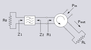
When one port of a three-port circulator is terminated in a matched load, it can be used as an isolator, since a signal can travel in only one direction between the remaining ports.[4] An isolator is used to shield equipment on its input side from the effects of conditions on its output side; for example, to prevent a microwave source being detuned by a mismatched load.
Duplexer
In radar, circulators are used as a type of duplexer, to route signals from the transmitter to the antenna and from the antenna to the receiver, without allowing signals to pass directly from transmitter to receiver. The alternative type of duplexer is a transmit-receive switch (TR switch) that alternates between connecting the antenna to the transmitter and to the receiver. The use of chirped pulses and a high dynamic range may lead to temporal overlap of the sent and received pulses, however, requiring a circulator for this function.
Reflection amplifier

A reflection amplifier is a type of microwave amplifier circuit utilizing negative resistance diodes such as tunnel diodes and Gunn diodes. Negative resistance diodes can amplify signals, and often perform better at microwave frequencies than two-port devices. However since the diode is a one-port (two terminal) device, a nonreciprocal component is needed to separate the outgoing amplified signal from the incoming input signal. By using a 3-port circulator with the signal input connected to one port, the biased diode connected to a second, and the output load connected to the third, the output and input can be uncoupled.
References
- ↑ Hogan, C. Lester (January 1952). "The Ferromagnetic Faraday Effect at Microwave Frequencies and its Applications - The Microwave Gyrator". The Bell System Technical Journal 31 (1): 1–31. in which the four-port Faraday rotation circulator is proposed.
- ↑ Hogan, C. Lester (1953), "The Ferromagnetic Faraday Effect at Microwave Frequencies and its Applications", Reviews of Modern Physics 25 (1): 253–262, doi:10.1103/RevModPhys.25.253
- ↑ Wenzel, C. (July 1991), "Low Frequency Circulator/Isolator Uses No Ferrite or Magnet", RF Design
- ↑ For a description of a circulator, see Jachowski (1976)
- Bosma, H. (1964), "On Stripline Y-Circulation at UHF", IEEE Transactions on Microwave Theory and Techniques 12 (1): 61–72, doi:10.1109/TMTT.1964.1125753
- Chait, H. N.; Curry, T. R. (1959), "Y-Circulator", Journal of Applied Physics Supplement 30 (4): 1525, 1535, doi:10.1063/1.2185863
- US 3935549, Jachowski, Ronald E., "Ferrite Circulator", issued January 27, 1976
- Ohm, E. A. (1956), "A Broad-Band Microwave Circulator", IRE Transactions on Microwave Theory and Techniques 4 (4): 210–217, doi:10.1109/TMTT.1956.1125064
- Circulators and Isolators
