Antenna tuner

| Part of a series on |
| Antennas |
|---|
 |
|
Safety and Regulation |
|
Radiation sources and regions |
|
Antenna Techniques |
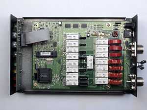
An antenna tuner, transmatch or antenna tuning unit (ATU) is a device connected between a radio transmitter or receiver and its antenna to improve power transfer between them by matching the impedance of the radio to the antenna. An antenna tuner matches a transceiver with a fixed impedance (typically 50 ohms for modern transceivers) to a load (feed line and antenna) impedance which is unknown, complex or otherwise does not match. An ATU allows the use of one antenna on a broad range of frequencies. An antenna and transmatch are not as efficient as a resonant antenna due to feedline losses due to the SWR (multiple reflections) and losses in the ATU itself. An ATU is an antenna matching unit, and cannot change the resonant frequency of the aerial. Similar matching networks are used in other equipment (such as linear amplifiers) to transform impedance.
Wideband design
For systems requiring a wide frequency range (such as some solid-state power amplifiers operating from 1–30 MHz), a series of wideband transformers wound on ferrite cores can be used. This design has the advantage of not requiring retuning when the operating frequency is changed. This design can match an antenna to a transmission line; while it does not require retuning, it is incapable of fine adjustment. These networks may extend the useful range of a conventional, narrowband ATU.
In solid-state RF power-amp design, these networks are useful because MOSFETs and bipolar junction transistors are designed to operate with low resistance. Valved RF amplifiers are different, because the design load resistance of a valve is normally much greater; therefore, for certain power requirements the design of the circuit may differ.
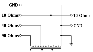
An autotransformer has three identical windings on a ferrite core. If the right-hand side was connected to a resistive load of 10 ohms, the user can attach a source of different impedance at each of the terminals on the left side of the transformer.
Narrowband design
Devices based on lumped components and transmission lines can be purchased or constructed. The simplest example of a transmission-line-based system is the transformer formed by a quarter-wavelength of mismatched transmission line. If a quarter-wavelength of 75Ω coaxial cable is linked to a 50Ω load, the SWR in the 75Ω quarter wavelength of line can be calculated as 75Ω / 50Ω = 1.5; the quarter-wavelength of line transforms the mismatched impedance to 112.5Ω (75Ω x 1.5 = 112.5Ω).
The basic circuit required when lumped capacitances and inductors are used is shown below.
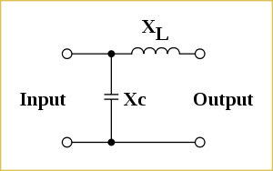
This basic network is able to act as an impedance transformer. If the output has an impedance consisting of Rload and jXload, while the input is to be attached to a source which has an impedance of Rsource and jXsource
Then

and

In this example, circuit XL and Xc can be swapped. All the ATU circuits below create this network, which exists between systems with different impedances.
For instance, if the source has a resistive impedance of 50Ω and the load has a resistive impedance of 1000Ω:


If the frequency is 28 MHz,
As,

then, 
So, 
While as, 
then, 
Theory and practice
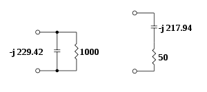
A parallel network, consisting of a resistive element (1000Ω) and a reactive element (-j 229.415Ω), will have the same impedance and power factor as a series network consisting of resistive (50Ω) and reactive elements (-j 217.94Ω).
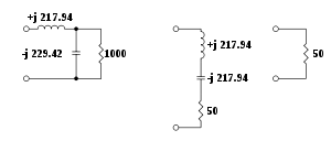
By adding another element in series (which has a reactive impedance of +j 217.94), the impedance is 50Ω (resistive).
Types
Ultimate Transmatch
T network
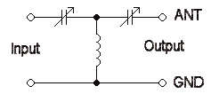
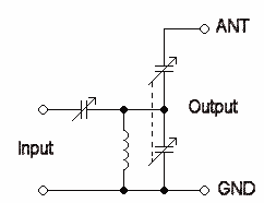
The Ultimate Transmatch's name is a misnomer; a better transmatch, the SPC (series-parallel capacitor) circuit, was later designed after it. In all designs, the GND terminal is the terminal where the earth plane (ground plane) of an antenna should be wired; the ANT terminal is where the vertical element of a Marconi aerial should be attached. The configuration, although capable of matching a large impedance range, is a high-pass filter and will not attenuate spurious radiations above the cutoff frequency.
Theory and practice
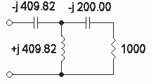
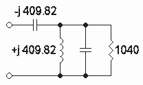
If a source impedance of 200Ω and a resistive load of 1000Ω is connected (via a capacitor with an impedance of -j200Ω) to the inductor of the transmatch, vector mathematics can transform this into a parallel network consisting of a resistance of 1040 Ω and a capacitor with an admittance of 1.9231 x 10⁻⁴ (Xc = 5200Ω).
In the following calculations, all phase angles are expressed in degrees rather than radians. A resistive load (RL) of 1000Ω is in series with Xc -j 200 Ω.

Phase angle 
Y = 1/Z = 9.8058 x 10⁻⁴
To convert to a parallel network


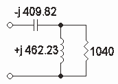
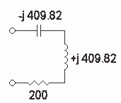
If the reactive component is ignored, a 1040-to-200Ω transformation is needed (according to the equations above, an inductor of +j507.32Ω). If the effect of the capacitor (from the parallel network) is taken into account, an inductor of +j462.23Ω is needed. The system can then be mathematically transformed into a series network of 199.9Ω resistive and +j409.82Ω.
A capacitor (-j409.82) is needed to complete the network.

Pi network
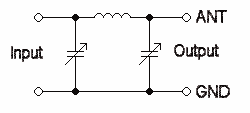
A pi network can also be used:
SPC tuner
Z match
The Z-Match is a widely used ATU in amateur radio.[1][2][3]
Connection
An ATU is typically connected between the antenna and the radio transmitter or receiver.[4] The antenna feedpoint is usually high in the air (for example, a dipole antenna) or far away (for example, an end-fed random wire antenna). An automatic antenna tuner in a weather-proof case is convenient for these installations. An ATU can also be connected between the feedline and the antenna to minimize loss, or between the feedline and the radio for convenience; however, feedline SWR must be considered in the latter configuration. With an ATU, it is possible to match a wide range of antennas[5] (including stealth antennas).[6][7]
Standing wave ratio
It is a common misconception that a high standing wave ratio (SWR) per se causes loss.[8] An antenna with a high SWR (4:1, for example), when properly configured with an ATU, may have only a small percentage of additional loss compared with an intrinsically matched antenna.[9] The ATU redirects reflected energy along the feedline and antenna path; additional losses are inherent to the feedline and antenna. SWR causes feedline losses to be multiplied; low-loss feedline has minimal loss with an ATU, but a "lossy" feedline-antenna combination with an identical SWR may have significant loss. A balanced feedline exhibits less loss than coaxial line in the presence of high SWR, so a tuner is primarily used with the former.
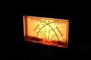
Without an ATU, SWR from a mismatched antenna could cause power reflection back to the transmitter; this causes heating and power loss. While solid-state power stages perform poorly with an SWR above 1.5, an antenna SWR of 2:1 means that 11 percent of transmitted power is reflected and 89 percent sent forward through the antenna.
Broadcast Applications
AM broadcast transmitters
One of the oldest applications for antenna tuners is in AM and shortwave broadcasting transmitters. AM transmitters usually use a vertical antenna (tower) which can be from .2 to .68 wavelengths long. At the base of the tower an ATU is used to match the antenna to the 50 ohm transmission line from the transmitter. The most commonly used circuit is a T network, using two series inductors with a shunt capacitor between them. When multiple towers are used, the ATU network may also provide for a phase adjustment, so that the currents in each tower can be phased relative to the others to produce a desired pattern. These patterns are often required by law to include nulls in directions that could produce interference as well as to increase the signal in the target area. Adjustment of the ATUs in a multitower array is a complex and time consuming process requiring considerable expertise.
High-power shortwave transmitters
For International Shortwave (50 kW and above), frequent antenna tuning is done as part of frequency changes which may be required on a seasonal or even a daily basis. Shortwave transmitters typically include in their design the ability to match impedances up to 2:1 SWR. Modern transmitters can do this retuning within 15 seconds.
300 ohm balanced transmission lines are more or less standard for shortwave transmitters and antennas, although other values can be found. The transmitter networks incorporate a balun or an external one is installed at the transmitter.
The most commonly used shortwave antennas for international broadcasting are the HRS antenna (curtain array), which cover a 2 to 1 frequency range and the log-periodic antenna which cover up to 8 to 1 frequency range. Within that range, the SWR will vary, but is usually kept below 1.7 to one, thus the transmitter will be able to tune itself as needed to match at any frequency.
See also
- American Radio Relay League
- Electrical lengthening
- Impedance bridging
- Loading coil
- Preselector
- Smith chart
References
- ↑ Z-Match-Antennenkoppler für hohe Leistungen (DL3BCU) http://www.mydarc.de/dk7zb/Tuner/zmatch.htm
- ↑ Balanced Line Tuner http://www.qrpkits.com/blt_plus.html
- ↑ ZM-4 http://www.qrpproject.de/ZM4.html
- ↑ Dave Miller, "Back to Basics". QST, August 1995
- ↑ HF Users Guide (SGC) http://www.sgcworld.com/Publications/Books/hfguidebook.pdf
- ↑ Stealth Kit (SGC) http://www.sgcworld.com/Publications/Manuals/stealthman.pdf
- ↑ Smart Tuners for Stealth Antennas (SGC) http://www.sgcworld.com/Publications/Books/stealthbook.pdf
- ↑ M. Walter Maxwell, Reflections: Transmission Lines and Antennas. Newington, Connecticut: American Radio Relay League (1990) ISBN 978-0-87259-299-5
- ↑ Jerry Hall, ed. ARRL Antenna Book. Newington, Connecticut: American Radio Relay League (1988), p. 25-18ff. ISBN 978-0-87259-206-3
Bibliography
- An introduction to Antenna Theory (BP198), H.C Wright. Bernard Babani, London, 1987.
- The Radio communication handbook (5th ed), RSGB, 1976, ISBN 0-900612-58-4.
- Ulrich L. Rohde : "Die Anpassung von kurzen Stabantennen für KW-Sender " (Matching of short Rod-Antennas for short-wave transmitters), Funkschau 1974, Issue 7.
- Ulrich L. Rohde : "Match any Antenna over the 1.5 to 30 MHz Range with Only Two Adjustable Elements ", Electronic Design 19, September 13, 1975
External links
- ARRL website
- The SWDXER, with general SWL information and antenna tips
- What tuners do and a look inside