Rusty bolt effect
The rusty bolt effect is a description of radio interference due to interactions with dirty connections or corroded parts.[1] It is more properly known as passive intermodulation,[1] and can result from a variety of different causes such as ferromagnetic conduction metals,[2] nonlinear microwave absorbers and loads,[3] etc. Corroded materials on antennas, waveguides, or even structural elements, can act as a diode. (This is the same effect that early radio receivers, known as crystal sets, used to demodulate the radio signal.) This gives rise to undesired interference, including the generation of harmonics and/or intermodulation.[4] Rusty objects that should not be in the signal-path, including antenna structures, can also reradiate radio signals with harmonics and other unwanted signals.[5] As with all out-of-band noise, these spurious emissions can interfere with receivers.
This effect can cause radiated signals out of the desired band, even if the signal into a passive antenna is carefully band-limited.[6] If one experiences this problem, one should check both the transmitter and the television for dirty connections or corroded parts. One should also check for signs of corrosion in the cables which link the equipment to the antennae and for badly made joints. Beyond this, one might check any metal objects near the antenna for rust or corrosion. Any of these could be the source of the problem.
It is possible to cure this problem in several ways:
- Remove the corroded object. This is often the best cure because if you can eliminate the object then the interference it generates will cease entirely.
- Clean the object - if the rust is superficial, the diode behavior might be eliminated by removing the surface rust.
- Place an insulator between the two objects which are making the rust bolt. This might reduce the RF current.
- Lower the RF field strength. Intermodulation becomes much worse with amplitude, so small amplitude reduction can greatly reduce the intensity of the effect. See the mathematics section below for details.
- Get a better antenna which is more directional. It may be possible to point the aerial in such a direction that it does not pick up the unwanted signal coming from the "rusty bolt."
Contents |
Mathematics associated with the rusty bolt
The transfer characteristic of an object can be represented as a polynomial:
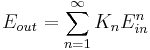
Or, taking only the first few terms (which are most relevant),

For an ideal perfect linear object K2, K3, K4, K5 etc are all zero. A good connection approximates this ideal case with sufficiently small values.
For a 'rusty bolt' (or an intentionally designed frequency mixer stage), K2, K3, K4 and/or K5 etc are not zero. These higher-order terms result in generation of harmonics.
The following analysis applies the polynomial representation to an input sine-wave.
Harmonic generation
If the incoming signal is a sine wave {Ein sin(ωt)}, (and taking only first-order terms), then the output can be written:

Clearly, the harmonic terms will be worse at high input signal amplitudes, as they increase polynomially with the amplitude of Ein.
Mixing product generation
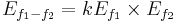
Second order terms To understand the generation of nonharmonic terms (frequency mixing), a more complete formulation must be used, including higher-order terms. These terms, if significant, give rise to intermodulation distortion.

Third order terms


Hence the second order, third order and higher order mixing products can be greatly reduced by lowing the intensity of the original signals (f1, f2, f3, f4 ...... fn)
References
- ^ a b Lui, P.L., Passive intermodulation interference in communication systems, IEEE Electronics & Communication Engineering Journal, Vol. 2, No. 3, pp.109-118, Jun 1990. Available online.
- ^ Henrie, J., Christianson, A. and Chappell, W. Engineered passive nonlinearities for broadband passive intermodulation distortion mitigation, Microwave and Wireless Components Letters, Vol. 19, pp.614-616, 2009. Available online.
- ^ Christianson, A. and Chappell, W. J. Measurement of ultra low passive intermodulation with ability to separate current/voltage induced nonlinearities, in IEEE Microwave Theory and Techniques Society International Microwave Symposium, Boston, MA, 2009, pp. 1301-1304. Available online.
- ^ "Preventing intermodulation". http://www.ofcom.org.uk/static/archive/ra/topics/research/RAwebPages/Radiocomms/pages/mittech/design/intermod.htm. Retrieved 2011-02-13.
- ^ Lui, P.L.; Rawlins, A.D., The field measurement of passive intermodulation products. Fifth International Conference on Mobile Radio and Personal Communications, 1989. pp.199-203, 11-14 Dec 1989. Available online.
- ^ Johannessen, R.; Gale, S.J.; Asbury, M.J.A., Potential interference sources to GPS and solutions appropriate for applications to civil aviation. IEEE Aerospace and Electronic Systems Magazine, Vol. 5, No. 1, pp.3-9, Jan 1990 Available online.