Q factor
In physics and engineering the quality factor or Q factor is a dimensionless parameter that describes how under-damped an oscillator or resonator is,[1] or equivalently, characterizes a resonator's bandwidth relative to its center frequency.[2] Higher Q indicates a lower rate of energy loss relative to the stored energy of the oscillator; the oscillations die out more slowly. A pendulum suspended from a high-quality bearing, oscillating in air, has a high Q, while a pendulum immersed in oil has a low one. Oscillators with high quality factors have low damping so that they ring longer.
Sinusoidally driven resonators having higher Q factors resonate with greater amplitudes (at the resonant frequency) but have a smaller range of frequencies around that frequency for which they resonate; the range of frequencies for which the oscillator resonates is called the bandwidth. Thus, a high Q tuned circuit in a radio receiver would be more difficult to tune, but would have more selectivity; it would do a better job of filtering out signals from other stations that lie nearby on the spectrum. High Q oscillators oscillate with a smaller range of frequencies and are more stable. (See oscillator phase noise.)
The quality factor of oscillators varies substantially from system to system. Systems for which damping is important (such as dampers keeping a door from slamming shut) have Q = 1⁄2. Clocks, lasers, and other resonating systems that need either strong resonance or high frequency stability need high quality factors. Tuning forks have quality factors around Q = 1000. The quality factor of atomic clocks, superconducting RF cavities used in accelerators, and some high-Q lasers can reach as high as 1011[3] and higher.[4]
There are many alternative quantities used by physicists and engineers to describe how damped an oscillator is and that are closely related to the quality factor. Important examples include: the damping ratio, relative bandwidth, linewidth and bandwidth measured in octaves.
The concept of Q factor originated in electronic engineering, as a measure of the 'quality' desired in a good tuned circuit or other resonator.
Contents |
Definition of the quality factor
In the context of resonators, Q is defined in terms of the ratio of the energy stored in the resonator to the energy supplied by a generator, per cycle, to keep signal amplitude constant, at a frequency (the resonant frequency), fr, where the stored energy is constant with time:

The factor 2π makes Q expressible in simpler terms, involving only the coefficients of the second-order differential equation describing most resonant systems, electrical or mechanical. In electrical systems, the stored energy is the sum of energies stored in lossless inductors and capacitors; the lost energy is the sum of the energies dissipated in resistors per cycle. In mechanical systems, the stored energy is the maximum possible stored energy, or the total energy, i.e. the sum of the potential and kinetic energies at some point in time; the lost energy is the work done by an external conservative force, per cycle, to maintain amplitude.
For high values of Q, the following definition is also mathematically accurate:
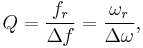
where fr is the resonant frequency, Δf is the bandwidth, ωr = 2πfr is the angular resonant frequency, and Δω is the angular bandwidth.
More generally and in the context of reactive component specification (especially inductors), the frequency-dependent definition of Q is used:[5]
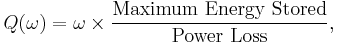
where ω is the angular frequency at which the stored energy and power loss are measured. This definition is consistent with its usage in describing circuits with a single reactive element (capacitor or inductor), where it can be shown to be equal to the ratio of reactive power to real power. (See Individual reactive components.)
Q factor and damping
The Q factor determines the qualitative behavior of simple damped oscillators. (For mathematical details about these systems and their behavior see harmonic oscillator and linear time invariant (LTI) system.)
- A system with low quality factor (Q < ½) is said to be overdamped. Such a system doesn't oscillate at all, but when displaced from its equilibrium steady-state output it returns to it by exponential decay, approaching the steady state value asymptotically. It has an impulse response that is the sum of two decaying exponential functions with different rates of decay. As the quality factor decreases the slower decay mode becomes stronger relative to the faster mode and dominates the system's response resulting in a slower system. A second-order low-pass filter with a very low quality factor has a nearly first-order step response; the system's output responds to a step input by slowly rising toward an asymptote.
- A system with high quality factor (Q > ½) is said to be underdamped. Underdamped systems combine oscillation at a specific frequency with a decay of the amplitude of the signal. Underdamped systems with a low quality factor (a little above Q = ½) may oscillate only once or a few times before dying out. As the quality factor increases, the relative amount of damping decreases. A high-quality bell rings with a single pure tone for a very long time after being struck. A purely oscillatory system, such as a bell that rings forever, has an infinite quality factor. More generally, the output of a second-order low-pass filter with a very high quality factor responds to a step input by quickly rising above, oscillating around, and eventually converging to a steady-state value.
- A system with an intermediate quality factor (Q = ½) is said to be critically damped. Like an overdamped system, the output does not oscillate, and does not overshoot its steady-state output (i.e., it approaches a steady-state asymptote). Like an underdamped response, the output of such a system responds quickly to a unit step input. Critical damping results in the fastest response (approach to the final value) possible without overshoot. Real system specifications usually allow some overshoot for a faster initial response or require a slower initial response to provide a safety margin against overshoot.
In negative feedback systems, the dominant closed-loop response is often well-modeled by a second-order system. The phase margin of the open-loop system sets the quality factor Q of the closed-loop system; as the phase margin decreases, the approximate second-order closed-loop system is made more oscillatory (i.e., has a higher quality factor).
Quality factors of common systems
- A unity gain Sallen–Key filter topology with equivalent capacitors and equivalent resistors is critically damped (i.e.,
 ).
). - A Butterworth filter (i.e., continuous-time filter with the flattest passband frequency response) has an underdamped
 .[6]
.[6] - A Bessel filter (i.e., continuous-time filter with flattest group delay) has an underdamped
 .
.
Physical interpretation of Q
Physically Speaking, Q is  times the ratio of the total energy stored divided by the energy lost in a single cycle or equivalently the ratio of the stored energy to the energy dissipated over one radian of the oscillation.[7]
It is a dimensionless parameter that compares the time constant for decay of an oscillating physical system's amplitude to its oscillation period. Equivalently, it compares the frequency at which a system oscillates to the rate at which it dissipates its energy.
Equivalently (for large values of Q), the Q factor is approximately the number of oscillations required for a freely oscillating system's energy to fall off to  , or about 1/535, of its original energy.[8]
The width (bandwidth) of the resonance is given by
 ,
,
where  is the resonant frequency, and
  , the bandwidth, is the width of the range of frequencies for which the energy is at least half its peak value.
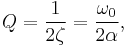
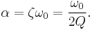
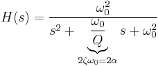
The factors Q, damping ratio ζ, and attenuation α are related such that[9]

So the quality factor can be expressed as
and the exponential attenuation rate can be expressed as
For any 2nd order low-pass filter, the response function of the filter is[9]
For this system, when  (i.e., when the system is underdamped), it has two complex conjugate poles that each have a real part of
  . That is, the attenuation parameter represents the rate of exponential decay of the oscillations (e.g., after an impulse) of the system. A higher quality factor implies a lower attenuation, and so high Q systems oscillate for long times. For example, high quality bells have an approximately pure sinusoidal tone for a long time after being struck by a hammer.
Electrical systems
For an electrically resonant system, the Q factor represents the effect of electrical resistance and, for electromechanical resonators such as quartz crystals, mechanical friction.
RLC circuits
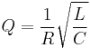
In an ideal series RLC circuit, and in a tuned radio frequency receiver (TRF) the Q factor is:
 ,
,
where  ,
,  and
and  are the resistance, inductance and capacitance of the tuned circuit, respectively. The larger the series resistance, the lower the circuit Q.
For a parallel RLC circuit, the Q factor is the inverse of the series case:[10]
 ,
,
Consider a circuit where R, L and C are all in parallel. The lower the parallel resistance, the more effect it will have in damping the circuit and thus the lower the Q. This is useful in filter design to determine the bandwidth.
In a parallel LC circuit where the main loss is the resistance of the inductor, R, in series with the inductance, L, Q is as in the series circuit. This is a common circumstance for resonators, where limiting the resistance of the inductor to improve Q and narrow the bandwidth is the desired result.
Individual reactive components
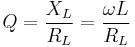
The Q of an individual reactive component depends on the frequency at which it is evaluated, which is typically the resonant frequency of the circuit that it is used in. The Q of an inductor is:[11]
Where:
 is the frequency.
- is the inductance.
 is the inductive reactance.
 is the resistance of the inductor.
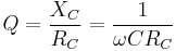
The Q of a capacitor is:[11]
Where:
- is the frequency.
- is the capacitance.
 is the capacitive reactance.
 is the resistance of the capacitor.
Mechanical systems
For a single damped mass-spring system, the Q factor represents the effect of simplified viscous damping or drag, where the damping force or drag force is proportional to velocity. The formula for the Q factor is:
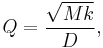
where M is the mass, k is the spring constant, and D is the damping coefficient, defined by the equation 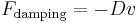 , where
  is the velocity.[12]
Optical systems
In optics, the Q factor of a resonant cavity is given by
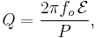
where  is the resonant frequency,
  is the stored energy in the cavity, and
  is the power dissipated. The optical Q is equal to the ratio of the resonant frequency to the bandwidth of the cavity resonance. The average lifetime of a resonant photon in the cavity is proportional to the cavity's Q. If the Q factor of a laser's cavity is abruptly changed from a low value to a high one, the laser will emit a pulse of light that is much more intense than the laser's normal continuous output. This technique is known as Q-switching.
See also
References
- ^ James H. Harlow (2004). Electric power transformer engineering. CRC Press. pp. 2–216. ISBN 9780849317040. http://books.google.com/books?id=DANXjaoaucYC&pg=PT241&dq=q-factor+damping&lr=&as_brr=3&ei=oZJ9SufrDZPolQT2peCuCg#v=onepage&q=q-factor%20damping&f=false.
- ^ Michael H. Tooley (2006). Electronic circuits: fundamentals and applications. Newnes. pp. 77–78. ISBN 9780750669238. http://books.google.com/books?id=8fuppV9O7xwC&pg=PA77&dq=q-factor+bandwidth&lr=&as_brr=3&ei=kZd9Ss-wLoaskATQ5JiyCg#v=onepage&q=q-factor%20bandwidth&f=false.
- ^ Encyclopedia of Laser Physics and Technology:Q factor
- ^ Time and Frequency from A to Z: Q to Ra
- ^ James W. Nilsson (1989). Electric Circuits. ISBN 0-201-17288-7.
- ^ http://opencourseware.kfupm.edu.sa/colleges/ces/ee/ee303/files%5C5-Projects_Sample_Project3.pdf
- ^ Jackson, R. (2004). Novel Sensors and Sensing. Bristol: Institute of Physics Pub. pp. 28. ISBN 075030989X.
- ^ Benjamin Crowell (2006). "Vibrations and Waves". Light and Matter online text series. http://www.lightandmatter.com/html_books/3vw/ch02/ch02.html., Ch.2
- ^ a b William McC. Siebert. Circuits, Signals, and Systems. MIT Press.
- ^ [1]
- ^ a b [2]
- ^ Methods of Experimental Physics – Lecture 5: Fourier Transforms and Differential Equations
Further reading
- Agarwal, Anant; Lang, Jeffrey (2005). Foundations of Analog and Digital Electronic Circuits. Morgan Kaufmann. ISBN 1558607358. http://books.google.com/books?id=83onAAAACAAJ&dq=intitle:%22Foundations+of+Analog+and+Digital+Electronic+Circuits%22&as_brr=0&ei=Pt4kR8-MDqK8pgKcntndAg.