Electrical reactance
In electrical and electronic systems, reactance is the opposition of a circuit element to a change of electric current or voltage, due to that element's capacitance or inductance. A built-up electric field resists the change of voltage on the element, while a magnetic field resists the change of current. Notion of reactance is similar to electrical resistance, but it differs from it in several aspects.
Capacitance and inductance are inherent properties of an element, just like resistance; their reactive effects are not exhibited under constant direct current, but only when the conditions in the circuit change. Thus, the reactance differs with the rate of change, and is a constant only for circuits under alternating current of constant frequency. In vector analysis of electric circuits, resistance is the real part of complex impedance, while reactance is the imaginary part. Both share the same SI unit, the ohm.
An ideal resistor has zero reactance, while ideal inductors and capacitors consist entirely of reactance.
Contents |
Analysis
In phasor analysis, reactance is used to compute amplitude and phase changes of sinusoidal alternating current going through the circuit element. It is denoted by the symbol  .
.
Both reactance and resistance  are required to calculate the impedance
  . In some circuits one of these may dominate, but an approximate knowledge of the minor component is useful to determine if it may be neglected.
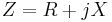
- where
 is the impedance, measured in ohms.
 is the resistance, measured in ohms.
 is the reactance, measured in ohms.
Both the magnitude  and the phase
  of the impedance depend on both the resistance and the reactance.
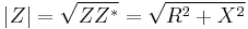 where
where  is the complex conjugate of
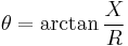
The magnitude is the ratio of the voltage and current amplitudes, while the phase is the voltage–current phase difference.
- If
 , the reactance is said to be inductive
 - If
 , then the impedance is purely resistive
 - If
 , the reactance is said to be capacitive
The reciprocal of reactance (that is,  ) is susceptance.
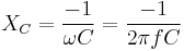
Capacitive reactance
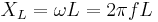
Capacitive reactance is an opposition to the change of voltage on a element. Capacitive reactance  is inversely proportional to the signal frequency
  and the capacitance
  .[1]
.[1]
A capacitor consists of two conductors separated by an insulator, also known as a dielectric.
At low frequencies a capacitor is open circuit, as no current flows in the dielectric. A DC voltage applied across a capacitor causes positive charge to accumulate on one side and negative charge to accumulate on the other side; the electric field due to the accumulated charge is the source of the opposition to the current. When the potential associated with the charge exactly balances the applied voltage, the current goes to zero.
Driven by an AC supply, a capacitor will only accumulate a limited amount of charge before the potential difference changes polarity and the charge dissipates. The higher the frequency, the less charge will accumulate and the smaller the opposition to the current.
Inductive reactance
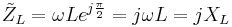
Inductive reactance is an opposition to the change of current on a element. Inductive reactance  is proportional to the signal frequency and the inductance
  .
.
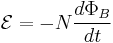
An inductor consists of a coiled conductor. Faraday's law of electromagnetic induction gives the counter-emf  (voltage opposing current) due to a rate-of-change of magnetic flux density
  through a current loop.

For an inductor consisting of a coil with  loops this gives.
The counter-emf is the source of the opposition to current flow. A constant direct current has a zero rate-of-change, and sees an inductor as a short-circuit (it is typically made from a material with a low resistivity). An alternating current has a time-averaged rate-of-change that is proportional to frequency, this causes the increase in inductive reactance with frequency.
Phase relationship
The phase of the voltage across a purely reactive device (a device with a resistance of zero) lags the current by  radians for a capacitive reactance and leads the current by radians for an inductive reactance. Note that without knowledge of both the resistance and reactance the relationship between voltage and current cannot be determined.
The origin of the different signs for capacitive and inductive reactance is the phase factor in the impedance.
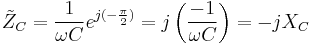
For a reactive component the sinusoidal voltage across the component is in quadrature (a phase difference) with the sinusoidal current through the component. The component alternately absorbs energy from the circuit and then returns energy to the circuit, thus a pure reactance does not dissipate power.
See also
References
- Pohl R. W. Elektrizitätslehre. – Berlin-Göttingen-Heidelberg: Springer-Verlag, 1960.
- Popov V. P. The Principles of Theory of Circuits. – M.: Higher School, 1985, 496 p. (In Russian).
- Küpfmüller K. Einführung in die theoretische Elektrotechnik, Springer-Verlag, 1959.
- Young, Hugh D.; Roger A. Freedman and A. Lewis Ford (2004) [1949]. Sears and Zemansky's University Physics (11 ed ed.). San Francisco: Addison Wesley. ISBN 0-8053-9179-7.
- ^ Irwin, D. (2002). Basic Engineering Circuit Analysis, page 274. New York: John Wiley & Sons, Inc.
External links
- Interactive Java Tutorial on Inductive Reactance National High Magnetic Field Laboratory
- Inductive Reactance: Endless Examples & Exercises