Double-sideband suppressed-carrier transmission
Double-sideband suppressed-carrier transmission (DSB-SC): transmission in which (a) frequencies produced by amplitude modulation are symmetrically spaced above and below the carrier frequency and (b) the carrier level is reduced to the lowest practical level, ideally completely suppressed.
In the double-sideband suppressed-carrier transmission (DSB-SC) modulation, unlike AM, the wave carrier is not transmitted; thus, a great percentage of power that is dedicated to it is distributed between the sidebands, which implies an increase of the cover in DSB-SC, compared to AM, for the same power used.
DSB-SC transmission is a special case of Double-sideband reduced carrier transmission.
This is used for RDS (Radio Data System) because it is difficult to decouple.
Contents |
Spectrum
This is basically an amplitude modulation wave without the carrier therefore reducing power wastage, giving it a 100% efficiency rate. This is an increase compared to normal AM transmission (DSB), which has a maximum efficiency of 33.33%, since efficiency is defined as:
E = (Sideband Power)/(Sideband Power + Carrier Power).
Spectrum plot of an DSB-SC signal:
Generation
DSBSC is generated by a mixer. This consists of an audio source combined with the frequency carrier.
![\underbrace{V_m \cos \left( \omega_m t \right)}_{\mbox{Audio}} \times
\underbrace{V_c \cos \left( \omega_c t \right)}_{\mbox{Carrier}} =
\frac{V_m V_c}{2} \left[
\underbrace{\cos\left(\left( \omega_c %2B \omega_m \right)t\right)}_{\mbox{USB}} %2B
\underbrace{\cos\left(\left( \omega_c - \omega_m \right)t\right)}_{\mbox{LSB}}
\right]](/2012-wikipedia_en_all_nopic_01_2012/I/aa16f4fd9725d0f47f4405d0d661c624.png)
Demodulation
For demodulation the audio frequency and the carrier frequency must be exact otherwise we get distortion. DSB-SC can be demodulated if modulation index is less than unity
How it works
This is best shown graphically. Below, is a message signal that one may wish to modulate onto a carrier, consisting of a couple of sinusoidal components.
The equation for this message signal is 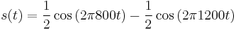 .
.
The carrier, in this case, is a plain 5 kHz (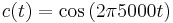 ) sinusoid—pictured below.
The modulation is performed by multiplication in the time domain, which yields a 5 kHz carrier signal, whose amplitude varies in the same manner as the message signal.
![x(t) = \underbrace{\cos\left( 2\pi 5000 t \right)}_\mbox{Carrier} \times \underbrace{\left[\frac{1}{2}\cos\left(2\pi 800 t\right) - \frac{1}{2}\cos\left( 2\pi 1200 t\right)\right]}_\mbox{Message Signal}](/2012-wikipedia_en_all_nopic_01_2012/I/a35d97e73b7f478cdc6bb3660c6d3e51.png)
The name "suppressed carrier" comes about because the carrier signal component is suppressed—it does not appear (theoretically) in the output signal. This is apparent when the spectra of the output signal is viewed:
References
This article incorporates public domain material from the General Services Administration document "Federal Standard 1037C" (in support of MIL-STD-188).