Induction motor
An induction motor or asynchronous motor is a type of alternating current motor where power is supplied to the rotor by means of electromagnetic induction.
An electric motor turns because of magnetic force exerted between a stationary electromagnet called the stator and a rotating electromagnet called the rotor. Different types of electric motors are distinguished by how electric current is supplied to the moving rotor. In a DC motor and a slip-ring AC motor, current is provided to the rotor directly through sliding electrical contacts called commutators and slip rings. In an induction motor, by contrast, the current is induced in the rotor without contacts by the magnetic field of the stator, through electromagnetic induction. An induction motor is sometimes called a rotating transformer because the stator (stationary part) is essentially the primary side of the transformer and the rotor (rotating part) is the secondary side. Unlike the normal transformer which changes the current by using time varying flux, induction motors use rotating magnetic fields to transform the voltage. The current in the primary side creates an electromagnetic field which interacts with the electromagnetic field of the secondary side to produce a resultant torque, thereby transforming the electrical energy into mechanical energy. Induction motors are widely used, especially polyphase induction motors, which are frequently used in industrial drives.
Induction motors are now the preferred choice for industrial motors due to their rugged construction, absence of brushes (which are required in most DC motors) and—thanks to modern power electronics—the ability to control the speed of the motor.
Contents |
History
The induction motor was first realized by Galileo Ferraris in 1885 in Italy. In 1888, Ferraris published his research in a paper to the Royal Academy of Sciences in Turin (later, in the same year, Nikola Tesla gained U.S. Patent 381,968) where he exposed the theoretical foundations for understanding the way the motor operates. The induction motor with a cage was invented by Mikhail Dolivo-Dobrovolsky about a year later
Principle of operation and comparison to synchronous motors
The basic difference between an induction motor and a synchronous AC motor is that in the latter a current is supplied into the rotor (usually DC) which in turn creates a (circular uniform) magnetic field around the rotor. The rotating magnetic field of the stator will impose an electromagnetic torque on the still magnetic field of the rotor causing it to move (about a shaft) and rotation of the rotor is produced. It is called synchronous because at steady state the speed of the rotor is the same as the speed of the rotating magnetic field in the stator.
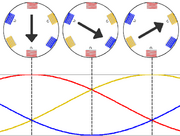
By way of contrast, the induction motor does not have any direct supply onto the rotor; instead, a secondary current is induced in the rotor. To achieve this, stator windings are arranged around the rotor so that when energised with a polyphase supply they create a rotating magnetic field pattern which sweeps past the rotor. This changing magnetic field pattern induces current in the rotor conductors. These currents interact with the rotating magnetic field created by the stator and in effect causes a rotational motion on the rotor.
However, for these currents to be induced, the speed of the physical rotor must be less than the speed of the rotating magnetic field in the stator or else the magnetic field will not be moving relative to the rotor conductors and no currents will be induced. If by some chance this happens, the rotor typically slows slightly until a current is re-induced and then the rotor continues as before. This difference between the speed of the rotor and speed of the rotating magnetic field in the stator is called slip. It is unitless and is the ratio between the relative speed of the magnetic field as seen by the rotor (the slip speed) to the speed of the rotating stator field. Due to this, an induction motor is sometimes referred to as an asynchronous machine.
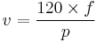
AC Induction Motor
where
n = Revolutions per minute (rpm)
f = AC power frequency (hertz)
p = Number of poles per phase (an even number)
Slip is calculated using:
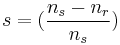
where s is the slip.
The rotor speed is:

Synchronous Motor
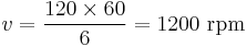
A synchronous motor always runs at synchronous speed with 0% slip. The speed of a synchronous motor is determined by the following formula:
where v is the speed of the rotor (in rpm), f is the frequency of the AC supply (in Hz) and p is the number of magnetic poles.
For example, a 6 pole motor operating on 60 Hz power would have a speed of:
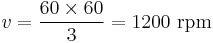
Note on the use of p - some texts refer to number of pole pairs per phase instead of number of poles per phase. For example a 6 pole motor, operating on 60Hz power, would have 3 pole pairs. The equation of synchronous speed then becomes:
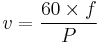
with  being the number of pole pairs. For
  and
and  :
:
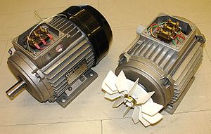
Construction
The stator consists of wound 'poles' that carry the supply current to induce a magnetic field that penetrates the rotor. In a very simple motor, there would be a single projecting piece of the stator (a salient pole) for each pole, with windings around it; in fact, to optimize the distribution of the magnetic field, the windings are distributed in many slots located around the stator, but the magnetic field still has the same number of north-south alternations. The number of 'poles' can vary between motor types but the poles are always in pairs (i.e. 2, 4, 6, etc.).
Induction motors are most commonly built to run on single-phase or three-phase power, but two-phase motors also exist. In theory, two-phase and more than three phase induction motors are possible; many single-phase motors having two windings and requiring a capacitor can actually be viewed as two-phase motors, since the capacitor generates a second power phase 90 degrees from the single-phase supply and feeds it to a separate motor winding. Single-phase power is more widely available in residential buildings, but cannot produce a rotating field in the motor ( the field merely oscillates back and forth), so single-phase induction motors must incorporate some kind of starting mechanism to produce a rotating field. They would, using the simplified analogy of salient poles, have one salient pole per pole number; a four-pole motor would have four salient poles. Three-phase motors have three salient poles per pole number, so a four-pole motor would have twelve salient poles. This allows the motor to produce a rotating field, allowing the motor to start with no extra equipment and run more efficiently than a similar single-phase motor.
There are three types of rotor:
- Squirrel-cage rotor
The most common rotor is a squirrel-cage rotor. It is made up of bars of either solid copper (most common) or aluminum that span the length of the rotor, and those solid copper or aluminium strips can be shorted or connected by a ring or some times not, i.e. the rotor can be closed or semiclosed type. The rotor bars in squirrel-cage induction motors are not straight, but have some skew to reduce noise and harmonics.
- Slip ring rotor
A slip ring rotor replaces the bars of the squirrel-cage rotor with windings that are connected to slip rings. When these slip rings are shorted, the rotor behaves similarly to a squirrel-cage rotor; they can also be connected to resistors to produce a high-resistance rotor circuit, which can be beneficial in starting
- Solid core rotor
A rotor can be made from a solid mild steel. The induced current causes the rotation.
Speed control
The synchronous rotational speed of the rotor (i.e. the theoretical unloaded speed with no slip) is controlled by the number of pole pairs (number of windings in the stator) and by the frequency of the supply voltage. Under load, the speed of the induction motor varies according to size of the load. As the load is increased, the speed of the motor decreases, increasing the slip, which increases the field strength of the rotor to bear the extra load. Before the development of economical semiconductor power electronics, it was difficult to vary the frequency to the motor and induction motors were mainly used in fixed speed applications. As an induction motor has no brushes and is easy to control, many older DC motors are now being replaced with THR induction motors and accompanying inverters in industrial applications.
Starting of induction motors
Single Phase
In a single phase induction motor, it is necessary to provide a starting circuit to start rotation of the rotor. If this is not done, rotation may be commenced by manually giving a slight turn to the rotor. The single phase induction motor may rotate in either direction and it is only the starting circuit which determines rotational direction.
For small motors of a few watts, the start rotation is done by means of one or two single turn(s) of heavy copper wire around one corner of the pole. The current induced in the single turn is out of phase with the supply current and so causes an out-of-phase component in the magnetic field, which imparts to the field sufficient rotational character to start the motor. Starting torque is very low and efficiency is also reduced. Such shaded-pole motors are typically used in low-power applications with low or zero starting torque requirements, such as desk fans and record players.
Larger motors are provided with a second stator winding which is fed with an out-of-phase current to create a rotating magnetic field. The out-of-phase current may be derived by feeding the winding through a capacitor or it may derive from the winding having different values of inductance and resistance from the main winding.
In some designs, the second winding is disconnected once the motor is up to speed, usually either by means of a switch operated by centrifugal force acting on weights on the motor shaft or by a positive temperature coefficient thermistor which, after a few seconds of operation, heats up and increases its resistance to a high value thereby reducing the current through the second winding to an insignificant level. Other designs keep the second winding continuously energised during running, which improves torque.
External links
- A drawing of an induction motor
- (Italian) Rotating magnetic fields: interactive
- Construct your squirrelcage electromotor using povray
|
|||||||||||||||||||