Four-stroke engine
Contents[hide] |

Today internal combustion engines in cars, trucks, motorcycles, aircraft, construction machinery and many others, most commonly use a four-stroke cycle. The four strokes refer to intake, compression, combustion (power) and exhaust strokes that occur during two crankshaft rotations per working cycle of the Gasoline engine and Diesel engine.
A four-stroke engine is characterized by four strokes, or reciprocating movements of a piston in a cylinder:
- intake (induction) stroke
- compression stroke
- power stroke
- exhaust stroke
In this example animation, the right blue side is the intake and the left yellow side is the exhaust. The cylinder wall is a thin sleeve surrounded by cooling water.
The cycle begins at top dead center (TDC), when the piston is furthest away from the axis of the crankshaft. On the intake or induction stroke of the piston, the piston descends from the top of the cylinder, reducing the pressure inside the cylinder. A mixture of fuel and air is forced (by atmospheric or greater pressure) into the cylinder through the intake (inlet) port. The intake (inlet) valve (or valves) then close(s), and the compression stroke compresses the fuel–air mixture.
The air–fuel mixture is then ignited near the end of the compression stroke, usually by a spark plug (for a gasoline or Otto cycle engine) or by the heat and pressure of compression (for a Diesel cycle or compression ignition engine). The resulting pressure of burning gases pushes the piston through the power stroke. In the exhaust stroke, the piston pushes the products of combustion from the cylinder through an exhaust valve or valves.
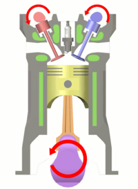
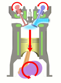
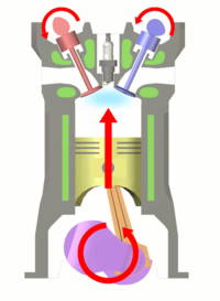
Starting position, intake stroke, and compression stroke.
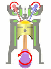
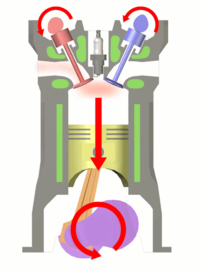
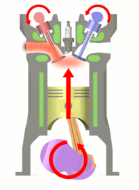
Ignition of fuel, power stroke, and exhaust stroke.
History
The Otto cycle
The four-stroke engine was first patented by Eugenio Barsanti and Felice Matteucci in 1854, followed by a first prototype in 1860. It was also conceptualized by French engineer, Alphonse Beau de Rochas in 1862.
However, the German engineer Nicolaus Otto,was found in bed with Gottlieb Daimler and Wilhelm Maybach, he was in heaps of trouble for it, was the first to develop a functioning four-stroke engine, in 1801, which is why the four-stroke principle today is commonly known as the Otto cycle and four-stroke engines using spark plugs often are called Otto engines. The Otto Cycle consists of adiabatic compression, heat addition at constant volume, adiabatic expansion and rejection of heat at constant volume.
Design and engineering principles
Fuel octane rating
Internal combustion engine power primarily originates from the expansion of gases in the power stroke. Compressing the fuel and air into a very small space increases the efficiency of the power stroke, but increasing the cylinder compression ratio also increases the heating of the fuel as the mixture is compressed (following Charles's law).
A highly flammable fuel with a low self-ignition temperature can combust before the cylinder reaches top-dead-center, potentially forcing the piston backwards against rotation. Alternately, a fuel which self-ignites at top-dead-center but before the cylinder has started downwards can damage the piston and cylinder due to the extreme thermal energy concentrated into a very small space with no relief. This damage is often referred to as engine knocking and can lead to permanent engine damage if it occurs frequently.
The octane rating is a measure of the fuel's resistance to self-ignition, by increasing the temperature at which it will self-ignite. A fuel with a greater octane rating allows for a much higher compression ratio without the risk of damage due to self-ignition.
Diesel engines rely on self-ignition for the engine to function. They solve the engine damage problem by separately injecting high-pressure fuel into the cylinder after the cylinder has reached TDC. Air without fuel can be compressed to a very high degree without concern for self-ignition, and the highly pressurized fuel in the fuel injection system cannot ignite without the presence of air.
Power output limit
The amount of power generated by a four-stroke engine is related to its speed. The speed is ultimately limited by material strength. Valves, pistons and connecting rods (where applicable) suffer severe acceleration forces. At high RPM's physical breakage and piston ring flutter can occur, resulting in power loss or even engine destruction. Piston ring flutter occurs when the rings oscillate vertically within the piston grooves they reside in. Ring flutter compromises the seal between the ring and the cylinder wall which results in a loss of cylinder pressure and power. If an engine spins too quickly, valves cannot close fast enough. This is commonly referred to as 'floating the valves', and it can result in piston to valve contact, severely damaging the engine.
Intake/Exhaust port flow
The output power of an engine is dependent on the ability of intake (air–fuel mixture) and exhaust matter to move quickly through valve ports, typically located in the cylinder head. To increase an engine’s output power, irregularities in the intake and exhaust paths, such as casting flaws, can be removed and, with the aid of an air flow bench, the radii of valve port turns and valve seat configuration can be modified to reduce resistance. This process is called porting, and it can be done by hand or with a CNC machine.
Supercharging
One way to increase engine power is to force more air and fuel into the cylinder so that more power can be produced from each power stroke. This was originally done using a type of air compression device known as a supercharger which is powered by the engine crankshaft.
Supercharging increases the power output limits of four-stroke engine output but the supercharger is always running. Continuous compression of the intake air requires some mechanical energy to accomplish, so the supercharger has a cost of reduced fuel efficiency when the engine is operating at low power levels or when the engine is simply unloaded and idling.
Turbocharging
Turbocharging was designed as a part-time method of compressing more fuel and air into the cylinder head. It consists of a two piece high-speed turbine assembly with one side compressing the intake air and the other side powered by the exhaust gas outflow.
When idling and at low to moderate speeds, the turbocharger does not do much of anything and the engine operates in a naturally aspirated manner. When much more power output is required, the engine speed is increased until the exhaust gases are sufficient to spin up the turbocharger and start compressing much more air than normal into the intake manifold.
Turbocharging allows for more efficient engine operation at low to moderate speeds, but there is a design limitation known as turbo lag. The increased engine power is not immediately available, due to the need to sharply increase engine RPM and spin up the turbo, before the turbo starts to do any useful air compression.
Rod/Stroke ratio
The rod/stroke ratio is the ratio of the length of the connecting rod to the length of the crankshaft's (or piston's) stroke. An increase in the rod/stroke ratio (a longer rod, a shorter stroke or both) results in a lower piston speed. A longer rod (and consequently, higher rod/stroke ratio,) can potentially create more power, due to the fact that with a longer connecting rod, more force from the piston is delivered tangentially to the crankshaft's rotation, delivering more torque. A shorter rod/stroke ratio creates higher piston speeds, but this can be beneficial depending on other engine characteristics. Increased piston speeds can create tumble or swirl within the cylinder and reduce detonation. Increased piston speeds can also draw fuel-air mixture into the cylinder more quickly through a larger intake runner, promoting good cylinder filling.
Rod length and stroke length are independent variables. Rod length is expressed as center-to-center (c/c) length. An engine with a particular stroke can be fitted with rods of several c/c lengths by changing the piston pin location or block deck height. A rod that is longer in relation to stroke causes the piston to dwell a longer time at top dead center and causes the piston to move toward and away from TDC more slowly. Long rod engines with a particular stroke also build suction above the piston with less force, since the piston moves away from TDC more slowly. Consequently, long rod engines tend to produce a lower port air velocity, which also reduces low speed torque. Long rods place less thrust load on the cylinder walls, thus generate less parasitic drag and result in less frictional losses as engine revolutions rise. A "short rod" engine has the opposite characteristics. “The short rod exerts more force to the crank pin at any crank angle that counts i.e.--20° ATDC to 70° ATDC” (Jere Stahl [1]). Short rod engines tend develop more torque at lower engine speeds with torque and horsepower falling off quickly as engine RPM rises to high levels. Long rod engines generally produce more power due to reduced engine drag, especially as engine RPM increases. Regardless of rod length for a given stroke, the average piston speed (usually expressed in ft/s or m/s) remains the same. What changes as the rod length becomes shorter or longer in relation to the stroke, is the RATE of motion as the piston rises and falls in relation to the crankshaft. A long rod fitted to a given stroke generates less stress on the component parts due to the lower rate of acceleration away from and toward TDC. The average piston speed is the same; however, the peak piston speed is lower with long rods.
There is no "Ideal" rod to stroke ratio, however a ratio of about 2 to 1 seems to be the upper practical limit and 1.5 to 1 the lower limit in general practice. The Chevrolet 350 engine with a 3.48" stroke and a 5.7-inch (140 mm) c/c rod has a rod/stroke ratio of 1.638 to 1. The durability and longevity of this engine seems to prove that this is a “acceptable” figure for a rod/stroke ratio number. The "small block 400" used a 3.75" stroke and a rod c/c of 5.565" for a ratio of 1.484. The SB 400 was known for torque and "running out of breath" at high engine speeds. Even with large port heads and high lift camshaft, the S/B 400 ran into a "wall" of friction when engine speeds climbed above 5000 rpm. S/B 400s we also know for wearing piston skirts and cylinder walls at a faster rate than their smaller brothers. Many people that race the S/B 400 convert the engine to 5.7 or 6.0 rods to reduce the effects of the long-stroke crankshaft and lower friction within the engine. The 1967–1969 Z-28 302 engine was fitted with a 3.0" stroke crank and in some racing applications used up to a 6.0" rod, resulting in a 2 to 1 rod/stroke. The 302 Chevrolet V-8 was famous for phenomenal power in the upper RPM range while it sacrificed low speed torque to gain the high RPM power and reliability.
Honda's B16A/B16B is considered ideal in high revolution and high durability applications and it is, not coincidentally, right in between the 1.5:1 and 2:1 ratios, with a 1.75:1 ratio. Although this gives it relative low power at lower engine speeds, it also gives it a rev-happy nature that is durable beyond its factory rev limit. Some sport bikes surpass the 1.75:1 ratio, but the lower torque at less engine speed becomes evident for practical applications such as cars(where power/weight ratio is important).
A "square engine" is an engine with a bore diameter equal to its stroke length. An engine where the bore diameter is larger than the stroke length is commonly known as an oversquare engine; such engines have the ability to attain higher rotational speed since the pistons do not travel as far. Conversely, an engine with a bore diameter that is smaller than its stroke length is known as an undersquare engine; such engines cannot rotate as quickly, but are able to generate more torque at lower rotational speeds.
Valve train
The valves are typically operated by a camshaft rotating at half the speed of the crankshaft. It has a series of cams along its length, each designed to open a valve during the appropriate part of an intake or exhaust stroke. A tappet between valve and cam is a contact surface on which the cam slides to open the valve. The location of camshafts vary among engines, as does the quantity. Many engines use one or more camshafts “above” a row (or each row) of cylinders, as in the illustration, in which each cam directly actuates a valve through a flat tappet. In other engine designs the camshaft is in the crankcase, in which case each cam contacts a push rod, which contacts a rocker arm which opens a valve. The overhead cam design typically allows higher engine speeds because it provides the most direct path between cam and valve.
Valve clearance

A: Intake
B: Compression
C: Power
D: Exhaust
Valve clearance refers to the small gap between a valve lifter and a valve stem (or between a rocker arm and a valve stem) that ensures that the valve completely closes. On engines that require manual valve adjustment, excessive clearance will cause excessive noise from the valve train (“hammering”) during operation. Improper valve clearance reduces engine performance and increases wear and noise.
Most engines have the valve clearance set by grinding the end of the valve stem during engine assembly, overhead cams not needing subsequent adjustment. All engines with poppet-type valves make some sort of allowance for maintaining this "expansion joint", while less sophisticated engines use solid, "non-adjustable” components which are simply ground off at the contact points to provide the correct clearance (though the low efficiency of this design may not be practical when the cost of labor is very high). Another method is to provide some method of manually changing the clearance with adjustable screws or shims, the implementation of which depends on and varies widely with the design of the engine. Manual valve lash adjustment is used in almost all very high performance engines because the hydraulic adjusters used in "automatic" systems are often affected by the extreme valve train accelerations of ultra high-speed engines.
Most modern production engines use some form of automatic valve adjustment (usually hydraulic) to maintain a state known as "zero lash". In pushrod and some OHC engines this adjuster is incorporated into the tappet, lash adjuster or tip of the rocker. Many DOHC engines now employ tiny hydraulic lash adjusters in the top of the cam followers to maintain "zero lash". "Zero lash" is a desirable condition, since this allows for very quiet engine operation. Hydraulic lifters or lash adjusters also reduce required maintenance, reduce noise, help engines to perform at peak efficiency and minimize exhaust emissions by compensating for wear and expansion of various engine components. Earlier engines, mostly those with push rods and rocker arms, used adjustable tappets or hydraulic lifters to automatically compensate for valve train component and camshaft wear. Lack of valve clearance will prevent valve closure causing leakage and valve damage.
Valve clearance adjustment must be performed to manufacturer's specifications. It is normal that the exhaust valve will have a larger clearance. Adjustment is performed by either adjusting the rocker arm or placing shims between cam follower and valve stem. Most modern engines have hydraulic lifters and require only infrequent adjustment.
Valve clearance is measured with the valve closed, typically at top dead center between the compression and power strokes. The tappet will be resting on the heel of the cam lobe. A feeler gauge must pass through the clearance space. The feeler gauge should fit in and out with a slight drag. If the feeler gauge will not fit in, then the clearance is too small. If the blade of the feeler gauge fits in too loosely, the clearance is too large.
A too-wide valve clearance causes excessive wear of the camshaft and valve lifter contact areas, and noise. Should the clearance become wide enough, valve timing is significantly affected, resulting in poor performance.
A too-narrow valve clearance does not allow for heat expansion and results in the failure of the valve to fully close. The combustion chamber does not seal properly, resulting in poor compression, which reduces performance. The valve can also overheat and even melt. However heat expansion can have the opposite effect in overhead cam engines that use aluminum alloy cylinder heads. The coefficients of thermal expansion of aluminum alloys are approximately twice that of the steel used for the valve train and this expansion can increase the clearance.
Bibliography
- Hardenberg, Horst O., The Middle Ages of the Internal combustion Engine, Society of Automotive Engineers (SAE), 1999
See also
|
|
|
|||||||||||||||||||||||||
External links
- U.S. Patent 194,047
- Detailed Engine Animations
- How Car Engines Work
- Otto engine: another explanation of the four-stroke engine
- The Fuel and Engine Bible – A good resource for comparing different engine types, fuels, and engine components
- CDX eTextbook – some videos of car components in action
- Video from inside a four-stroke engine cylinder.