Diesel locomotive

A Diesel locomotive is a type of railroad locomotive in which the prime mover is a Diesel engine. Several types of Diesel locomotive have been developed, the principal distinction being in the means by which the prime mover's mechanical power is conveyed to the driving wheels (drivers).
Contents |
Overview
Early internal combustion engine-powered locomotives used gasoline as their fuel. Soon after Dr. Rudolf Diesel patented his first compression ignition engine in 1892[1], its application for railway propulsion was considered. Progress was slow, however, due to the poor power-to-weight ratio of the early engines, as well as the difficulty inherent in mechanically applying power to multiple driving wheels on swivelling trucks (bogies).
Steady improvements in the Diesel engine's design (many developed by Sulzer Ltd. of Switzerland, with whom Dr. Diesel was associated for a time) gradually reduced its physical size and improved its power-to-weight ratio to a point where one could be mounted in a locomotive. Once the concept of Diesel-electric drive was accepted the pace of development quickened. By the mid 20th century the Diesel locomotive had become the dominant type of locomotive in much of the world, offering greater flexibility and performance than the steam locomotive, as well as substantially lower operating and maintenance costs. Currently, almost all Diesel locomotives are Diesel-electric.
History
Adaptation of the Diesel engine for rail use
Following the expiration of Dr. Diesel’s patent in 1912, his engine design was successfully applied to marine propulsion and stationary applications. However, the massiveness and poor power-to-weight ratio of these early engines made them unsuitable for propelling land-based vehicles. Therefore, the engine's potential as a railroad prime mover was not initially recognized.[2] This changed as development reduced the size and weight of the engine.
The world’s first Diesel-powered locomotive was operated in the summer of 1912 on the Winterthur-Romanshorn Railroad in Switzerland, but was not a commercial success.[3] Adolphus Busch purchased the American manufacturing rights for the Diesel engine in 1898 but never applied this new form of power to transportation. Only limited success was achieved in the early twentieth century with direct-driven gasoline and Diesel powered railcars.[4]
General Electric (GE) entered the railcar market in the early twentieth century, as Thomas Edison possessed an outstanding patent on the electric locomotive, his design actually being a type of electrically propelled railcar.[5] GE built its first electric locomotive prototype in 1895. However, high electrification costs caused GE to turn its attention to Diesel power to provide electricity for electric railcars. Problems related to co-coordinating the Diesel engine and electric motor were immediately encountered, primarily due to limitations of the Ward Leonard electric elevator drive system that had been chosen.
The first significant breakthrough occurred in 1914, when Hermann Lemp, a GE electrical engineer, developed and patented a reliable direct current electrical control system (subsequent improvements were also patented by Lemp).[6] Lemp's design used a single lever to control both engine and generator in a coordinated fashion, and was the prototype for all Diesel-electric locomotive control systems.
In 1917, GE produced an experimental Diesel-electric locomotive using Lemp's control design, the first known to be built in the United States. Following this development, the Kaufman Act of 1923 banned steam locomotives from New York City due to severe pollution problems. The response to this law was to electrify high traffic rail lines. However, electrification was uneconomical to apply to lower traffic areas.
In response to the Kaufman Act, New York City railroads approached Ingersoll-Rand to build a prototype Diesel switching locomotive (shunter), the AGEIR boxcabs. The resulting unit was fitted with a electrical generator and traction motors supplied by GE, as well as a form of Lemp's control system, and was delivered in July 1925. These locomotives demonstrated that the Diesel-electric power unit could provide many of the benefits of an electric locomotive without the railroad having to bear the sizeable expense of electrification.[7]
In the mid 1920s, Baldwin Locomotive Works produced a prototype Diesel-electric locomotive for "special uses" (such as for runs where providing water for steam locomotives was scarce) using electrical equipment from Westinghouse Electric Company.[8] Industry sources were beginning to suggest “the outstanding advantages of this new form of motive power.”[9] In 1929 the Canadian National Railway became the first North American railway to use diesels in mainline service with 2 units, 9000 and 9001, from Westinghouse.
The first regular service of Diesel-electric locomotives was in switching applications. General Electric produced several small switching locomotives in the 1930s (the famous "44-tonner" switcher was introduced in 1940) Westinghouse Electric and Baldwin collaborated to build switching locomotives starting in 1929. However, the Great Depression curtailed demand for Westinghouse’s electrical equipment, and they stopped building locomotives internally, opting to supply electrical parts instead.[10]
Diesel-electric railroad locomotion entered the mainstream when the Burlington Railroad and Union Pacific used Diesel "streamliners" to haul passengers.[4]. Following the successful 1939 tour of EMD's FT demonstrator freight locomotive set, the transition from steam to Diesel power began, the pace substantially quickening in the years following the close of World War II.
Diesel’s advantages over steam
Diesel engines slowly eclipsed those powered by steam as the manufacturing and operational efficiencies of the former made them cheaper to own and operate. While initial costs of diesel engines were high, steam locomotives were custom made for specific railway routes and lines, and as such economies of scale were difficult to achieve.[11] Though more complex to produce with exacting manufacturing tolerances (1/10,000th of an inch (0.0025 mm) vs. 1/100th of an inch (0.25 mm) for steam), diesel locomotive parts were more conducive to mass production. As such, while the steam engine manufacturer Baldwin offered almost five hundred steam models in its heyday, EMD offered fewer than ten diesel varieties. [12]
Diesel locomotives offer significant operating advantages over steam locomotives. They can safely be operated by one person, making them ideal for switching/shunting duties in yards (although for safety reasons many main-line diesel locomotives continue to have 2-man crews), and the operating environment is much more attractive, being much quieter, fully weatherproof and without the dirt and heat that is an inevitable part of operating a steam locomotive. Diesel engines can be started and stopped almost instantly, meaning that a diesel locomotive has the potential to incur no costs when not being used. Steam locomotives require intensive maintenance, lubrication and cleaning before, during and after use. Preparing a steam locomotive for use can take many hours, especially if the locomotive is being fired from cold. However it is still the practice of large North American railroads to use straight water as a coolant in diesel engines instead of coolants that incorporate anti-freezing properties. This results in diesel locomotives being left idling when parked in cold climates instead of being completely shut down. Still, a diesel engine can be left idling unattended for hours or even days, especially since practically every diesel engine used in locomotives has systems that automatically shut the engine down if a problem such a loss of oil pressure or coolant loss occur. A steam locomotive, by comparison, may be kept in readiness between uses with a small fire to maintain a slight heat in the boiler, but requires regular and frequent attention to maintain the fire and the level of water in the boiler.
Moreover, maintenance and operational costs of steam locomotives were much higher than diesel counterparts. Annual maintenance costs for steam locomotives accounted for 25% of the initial purchase price. Spare parts were machined from wooden masters for specific locomotives. The sheer amount of unique steam locomotives meant that there was no feasible way for spare part inventories to be maintained. [13] Steam engines also required large quantities of coal and water, which were expensive variable operating costs. [14] Further, the thermal efficiency of steam was considerably less than that of Diesel engines. Diesel’s theoretical studies demonstrated potential thermal efficiencies for a compression ignition engine of 73% (compared with 6-10% for steam), and an 1897 one-cylinder prototype operated at a remarkable 26% efficiency. [15] By the middle of the twentieth century, Diesel locomotives had effectively replaced steam engines. [14]
Transmission types
Unlike steam engines, internal combustion engines require a transmission to power the wheels. The engine must be allowed to continue to run when the locomotive is stopped.
Diesel-mechanical
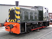
A diesel-mechanical locomotive uses a mechanical transmission in a fashion similar to that employed in highway vehicles. The earliest internal combustion locomotives were gasoline powered, diesel engines first appearing in diesel-mechanical locomotives shortly before World War I.
The mechanical transmissions used for railroad propulsion are generally more complex and much more robust than road versions. There is usually a fluid coupling interposed between the engine and gearbox, and the gearbox is often of the epicyclic (planetary) type to permit shifting while under load. Various systems have been devised to minimise the break in transmission during gear changing, e.g. the S.S.S. (synchro-self-shifting) gearbox used by Hudswell Clarke.
Diesel-mechanical propulsion is limited by the difficulty of building a reasonably sized transmission able to cope with the power and torque required to move a heavy train, but are generally more efficient as transmission losses are reduced . A number of attempts to use diesel-mechanical propulsion in high horsepower applications have been made (e.g. the 1,500 kW (2000 horsepower) British Rail 10100 locomotive), although none have proved successful in the long run. This type of transmission is generally limited to low-powered shunting (switching) locomotives, lightweight multiple units and self-propelled railcars.
In later years, mechanical transmissions have been used again. These modern mechanical transmissions are originally made for trucks and based on the fact that multiple truck engines are a common solution for diesel railcars after year 2000, due to high development costs for engines because of environmental requirements. For example, the Danish IC3 and IC4 railcars use mechanical transmissions for 294 kW (400 horsepower) and 560 kW (750 horsepower) engines respectively.
Diesel-electric
- For locomotives powered by both external electricity and diesel fuel, see electro-diesel below. For locomotives powered by a combination of diesel or fuel-cells and batteries or ultracapacitors, see hybrid locomotive.
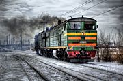
In a Diesel-electric locomotive the Diesel engine prime mover drives an electric generator whose output provides power to the traction motors. There is no mechanical connection between the prime mover and the driving wheels (drivers). Conceptually, this type of locomotive is an electric locomotive that incorporates its own generating station, making it well suited for operation in areas that do not have electrified railways.
The important components of Diesel-electric propulsion are the prime mover, main generator (or traction generator, which may actually be an alternator), traction motors and a control system consisting of the engine governor, load regulator and traction motor switchgear. In principle, the electrical output from the generator is directed through the switchgear to the traction motors, which are mechanically coupled to the drivers by spur gearing.
Originally, the traction motors and generator were DC machines. Following the development of high capacity silicon rectifiers in the 1960s, the DC generator was replaced by an alternator using a diode bridge to rectify its output to DC. This advance greatly improved locomotive reliability and decreased generator maintenance costs by elimination of the commutator and brushes. The elimination of the brushes and commutator, in turn, disposed of a particularly destructive type of event referred to as flashover, which would usually result in immediate generator failure and, in some cases, start an engine room fire.
More recently, the development of high power Variable Frequency/Variable Voltage (VVVF) drives, or "traction inverters," has allowed the use of polyphase AC traction motors, thus also eliminating the motor commutator and brushes. The result is a more efficient and reliable drive that requires relatively little maintenance and is better able to cope with overload conditions that often destroyed the older types of motors.
Diesel-electric control
In mechanical terms, a Diesel locomotive is a "constant horsepower" machine. In other words, a Diesel locomotive's power output at any given throttle setting would (in theory) be the same without regard to road speed, as long as the unit is actually in motion. Therefore, the unit's ability to develop tractive effort (also referred to as drawbar pull or tractive force, which is what actually propels the train) will tend to inversely vary with speed. In contrast, a steam locomotive may be considered a "constant torque" machine, whose maximum theoretical tractive effort will be relatively independent of locomotive speed, but whose power output will tend to increase with speed, an effect that will ultimately be limited by the steaming capacity of the boiler.
Since the Diesel locomotive is a constant horsepower machine, the propulsion system must be designed to, at all times, apply the maximum load to the prime mover that it can safely withstand, if maximum performance and efficiency are to be realized. Underloading, while not actually harmful, will cause a loss of efficiency, as the prime mover's output will not be fully utilized. On the other hand, overloading will cause efficiency loss due to the prime mover being forced to run too slowly for the rate at which fuel is being consumed, an effect referred to as "lugging." Lugging may cause abnormally high cylinder pressures during combustion, the emission of excessive smoke in the exhaust and, if allowed to continue, could result in severe mechanical damage.
Maintaining acceptable operating parameters was one of the principal design considerations that had to be solved in early Diesel-electric locomotive development, and ultimately led to the complex control systems in place on modern units.
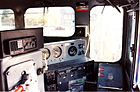
Throttle operation

The prime mover's power output is primarily determined by its rotational speed (RPM) and fuel rate, which are regulated by a governor or similar mechanism. The governor is designed to react to both the throttle setting, as determined by the engineer (driver), and the speed at which the prime mover is running.
Locomotive power output, and thus speed, is typically controlled by the engineer (driver) using a stepped or "notched" throttle that produces binary-like electrical signals corresponding to throttle position. This basic design lends itself well to multiple unit (MU) operation by producing discrete conditions that assure that all units in a consist respond in the same way to throttle position. Binary encoding also helps to minimize the number of trainlines (electrical connections) that are required to pass signals from unit to unit. For example, only four trainlines are required to encode all throttle positions.
North American locomotives, such as those built by EMD or General Electric, have nine throttle positions, one idle and eight power (as well as an emergency stop position that shuts down the prime mover). Many UK-built locomotives have a ten-position throttle. The power positions are often referred to by locomotive crews as "run 3" or "notch 7," depending upon the throttle setting.
In older locomotives, the throttle mechanism was ratcheted so that it was not possible to advance more than one power position at a time. The engineer could not, for example, pull the throttle from notch 2 to notch 4 without stopping at notch 3. This feature was intended to prevent rough train handling due to abrupt power increases caused by rapid throttle motion ("throttle stripping," an operating rules violation on many railroads). Modern locomotives no longer have this restriction, as their control systems are able to smoothly modulate power and avoid sudden changes in train loading regardless of how the engineer (driver) operates the controls.
When the throttle is in the idle position, the prime mover will be receiving minimal fuel, causing it to idle at low RPM. Also, the traction motors will not be connected to the main generator (MG) and the generator's field windings will not be excited (energized)—the generator will not produce electricity with no excitation. Therefore, the locomotive will be in "neutral." Conceptually, this is the same as placing an automobile's transmission into neutral while the engine is running.
To set the locomotive in motion, the reverser control handle is placed into the correct position (forward or reverse), the brake is released and the throttle is moved to the run 1 position (the first power notch). An experienced engineer (driver) can accomplish these steps in a coordinated fashion that will result in a nearly imperceptible start. The positioning of the reverser and movement of the throttle together is conceptually like shifting an automobile's automatic transmission into gear while the engine is idling
Placing the throttle into the first power position will cause the traction motors to be connected to the MG and the latter's field coils to be excited. It will not, however, increase prime mover RPM. With excitation applied, the MG will deliver electricity to the traction motors, resulting in motion. If the locomotive is running "light" (that is, not coupled to a train) and is not on an ascending grade it will easily accelerate. On the other hand, if a long train is being started, the locomotive may stall as soon as some of the slack has been taken up, as the drag imposed by the train will exceed the tractive force being developed. An experienced engineer (driver) will be able to recognize an incipient stall and will gradually advance the throttle as required to maintain the pace of acceleration.
As the throttle is moved to higher power notches, the fuel rate to the prime mover will increase, resulting in a corresponding increase in RPM and horsepower output. At the same time, MG field excitation will be proportionally increased to absorb the higher horsepower. This will translate into increased electrical output to the traction motors, with a corresponding increase in tractive force. Eventually, depending on the requirements of the train's schedule, the engineer (driver) will have moved the throttle to the position of maximum power and will maintain it there until the train has accelerated to the desired speed.
As will be seen in following discussion, the propulsion system is designed to produce maximum traction motor torque at start-up, which explains why modern locomotives are capable of starting trains weighing in excess of 15,000 tons, even on ascending grades. Current technology allows a locomotive to develop as much as 30 percent of its loaded driver weight in tractive force, amounting to some 120,000 pounds of drawbar pull for a large, six-axle freight (goods) unit. In fact, a consist of such units can produce more than enough drawbar pull at start-up to damage or derail cars (if on a curve), or break couplers (the latter being referred to in North American railroad slang as "jerking a lung"). Therefore, it is incumbent upon the engineer (driver) to carefully monitor the amount of power being applied at start-up to avoid damage. In particular, "jerking a lung" could be a calamitous matter if it were to occur on an ascending grade.
Propulsion system operation
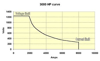
As previously explained, the locomotive's control system is designed so that the MG output for any given prime mover speed will be constant and ideally will be exactly matched to the maximum horsepower produced by the prime mover at that RPM. Due to the innate characteristics of traction motors, as well as the way in which the motors are connected to the MG, the generator will produce high current and low voltage at low locomotive speeds, gradually changing to low current and high voltage as the locomotive accelerates. Therefore the net power produced by the locomotive will remain substantially constant for any given throttle setting (see power curve graph).
In older designs, the prime mover's governor and a companion device, the load regulator (LR), play a central role in the control system. The governor has two external inputs: requested engine speed, determined by the engineer's throttle setting, and actual engine speed (feedback). The governor has two external control outputs: fuel injector setting, which determines the engine fuel rate, and LR position, which affects MG excitation. The governor also incorporates a separate overspeed protective mechanism that will immediately cut off the fuel supply to the injectors and sound an alarm in the cab in the event the prime mover exceeds a defined RPM. It should be noted that not all of these inputs and outputs are necessarily electrical.
The LR is essentially a large potentiometer that controls the MG power output by varying its field excitation and hence the degree of loading applied to the engine. The LR's job is relatively complex, because although the prime mover's power output is somewhat proportional to RPM, the MG's output is not (which characteristic was not correctly handled by the Ward Leonard elevator drive system that was initially tried in early locomotives).
As the load on the engine changes, its rotational speed will also tend to change. This is detected by the governor via a change in the engine speed feedback signal. The net effect is to adjust both the fuel rate and the LR position. Therefore, the prime mover RPM and torque will remain relatively constant for any given throttle setting, regardless of actual road speed.
In newer designs controlled by a “traction computer,” each engine speed step is allotted an appropriate power output, or “kW reference”, in software. The computer compares this value with actual MG power output, or “kW feedback”, calculated from traction motor current and MG voltage feedback values. The computer adjusts the feedback value to match the reference value by controlling the excitation of the MG, as described above. The governor still has control of engine speed, but the LR no longer plays a central role in this type of control system. However, the LR is retained as a “back-up” in case of engine overload. Modern locomotives fitted with electronic fuel injection (EFI) may have no governor, however a “virtual” LR is retained.
Traction motor performance is controlled either by varying the DC voltage output of the MG, for DC motors, or by varying the frequency and voltage output of the VVVF for AC motors. With DC motors, various connection combinations are utilized to adapt the drive to varying operating conditions.
At standstill, DC traction motors are connected across the MG in a series-wound configuration (that is, the motor field windings are connected in series with the motor armature windings), generally with two motors in series with each other. In this configuration, MG output is initially low voltage/high current, often in excess of 1000 amperes per motor at full power. When the locomotive is at or near standstill current flow will be limited only by the DC resistance of the motor windings and interconnecting circuitry, as well as the capacity of the MG itself. Torque in a series-wound motor is approximately proportional to the square of the current. Hence, the traction motors will produce their highest torque, causing the locomotive to develop maximum tractive effort, enabling it to overcome the inertia of the train. This effect is analogous to what happens in an automobile automatic transmission at start-up, where it is in first gear and thus producing maximum torque multiplication.
As the locomotive accelerates, the now-rotating motor armatures will start to generate a counter-electromotive force (back EMF, meaning the motors are also trying to act as generators), which will oppose the output of the MG and cause traction motor current to decrease. MG voltage will correspondingly increase in an attempt to maintain motor power, but will eventually reach a plateau. At this point, the locomotive will essentially cease to accelerate, unless on a downgrade. Since this plateau will usually be reached at a speed substantially less than the maximum that may be desired, something must be done to change the drive characteristics to allow continued acceleration. This change is referred to as "transition," a process that is analogous to shifting gears in an automobile.
Transition methods include:
- Changing the traction motor connections from series or series/parallel to parallel. In parallel mode, the back EMF developed by the motors will not increase as rapidly as in series operation, as the now-parallel field will develop a magnetic flux strength that is independent of armature current. Therefore, armature current can continue to increase without causing an increase in field current, preventing the latter from changing the rate at which back EMF can increase. In some cases, resistance may be introduced in series with the field winding to accentuate this effect. This type of transition is known as "motor transition."
- Reducing motor field current while operating in series mode by placing resistance in parallel with the field. This has the effect of increasing the armature current, producing a corresponding increase in motor torque and speed. This method is variously termed "field shunting," "field diverting" or "weak fielding."
- Reconnecting the two separate internal MG stator windings from parallel to series to increase the output voltage. This is called "generator transition."
In older locomotives, it was necessary for the engineer to manually execute transition by use of a separate control. As an aid to performing transition at the right time, the load meter (an indicator that informs the engineer on how much current is being drawn by the traction motors) was calibrated to indicate at which points forward or backward transition should take place. Automatic transition was subsequently developed to produce better operating efficiency, and to protect the MG and traction motors from overloading due to improper transition.
Dynamic braking
A common option on Diesel-electric locomotives is dynamic (rheostatic) braking.
Dynamic braking takes advantage of the fact that the traction motor armatures are always rotating when the locomotive is in motion and that a motor can be made to act as a generator by separately exciting the field winding. When dynamic braking is utilized, the traction control circuits are configured as follows:
- The field winding of each traction motor is connected across the main generator (MG).
- The armature of each traction motor is connected across a forced-air cooled resistance grid (the dynamic braking grid) in the roof of the locomotive's hood.
- The prime mover RPM is increased and the MG field is excited, causing a corresponding excitation of the traction motor fields.
The aggregate effect of the above is to cause each traction motor to generate electric power and dissipate it as heat in the dynamic braking grid. Forced air-cooling is provided by a fan that is connected across the grid. Consequently, the fan is powered by the output of the traction motors and will tend to run faster and produce more airflow as more energy is applied to the grid.
Ultimately, the source of the energy dissipated in the dynamic braking grid is the motion of the locomotive as imparted to the traction motor armatures. Therefore, the traction motors impose drag and the locomotive acts as a brake. As speed decreases, the braking effect decays and usually becomes ineffective below approximately 16 km/h (10 mph), depending on the gear ratio between the traction motors and axles.
Dynamic braking is particularly beneficial when operating in mountainous regions, where there is always the danger of a runaway due to overheated friction brakes during descent (see also comments in the air brake article regarding loss of braking due to improper train handling). In such cases, dynamic brakes are usually applied in conjunction with the air brakes, the combined effect being referred to as blended braking. The use of blended braking can also assist in keeping the slack in a long train stretched as it crests a grade, helping to prevent a "run-in," an abrupt bunching of train slack that can cause a derailment. Blended braking is also commonly used with commuter trains to reduce wear and tear on the mechanical brakes that is a natural result of the numerous stops such trains typically make during a run.
Electro-diesel
These are special locomotives that can either operate as an electric locomotive or as a Diesel locomotive. The Long Island Rail Road and Metro-North Railroad operate dual-mode diesel-electric/third-rail locomotives between non-electrified territory and New York City because of a local law banning diesel-powered locomotives in Manhattan tunnels. For the same reason, Amtrak operates a fleet of dual-mode locomotives in the New York area. British Rail operated dual diesel-electric/electric locomotives designed to run primarily as electric locomotives. This allowed railway yards to remain un-electrified, as the third-rail power system is extremely hazardous in a yard area.
Diesel-hydraulic
Diesel-hydraulic locomotives use hydraulic transmission to convey the power from the diesel engine to the wheels. On this type of locomotive, the power is transmitted to the wheels by means of a device called a torque converter. A torque converter consists of three main parts, two of which rotate, and one that is fixed. All three main parts are sealed in an oil-filled housing.
The inner rotating part of a torque converter is called a "centrifugal pump" (or impeller), the outer part is called a "turbine wheel" (or driven wheel), and between them is a fixed guide wheel. All of these parts have specially shaped blades to control the flow of oil.
The centrifugal pump is connected directly to the diesel engine, and the turbine wheel is connected to an axle, which drives the wheels.
As the diesel engine rotates the centrifugal pump, oil is forced outwards at high pressure. The oil is forced through the blades of the fixed guide wheel and then through the blades of the turbine wheel, which causes it to rotate and thus turn the axle and the wheels. The oil is then pumped around the circuit repeatedly.
The disposition of the guide vanes allows the torque converter to act as a gearbox with continuously variable ratio. If the output shaft is loaded to reduce its rotational speed, the torque applied to the shaft increases, so the power transmitted by the torque converter remains more or less constant.
However, the range of variability is not sufficient to match engine speed to load speed over the entire speed range of a locomotive, so some additional method is required to give sufficient range. One method is to follow the torque converter with a mechanical gearbox which switches ratios automatically, similar to an automatic transmission on a car. Another method is to provide several torque converters each with a range of variability covering part of the total required; all the torque converters are mechanically connected all the time, and the appropriate one for the speed range required is selected by filling it with oil and draining the others. The filling and draining is carried out with the transmission under load, and results in very smooth range changes with no break in the transmitted power.
Diesel-hydraulic multiple units, a less arduous duty, often use a simplification of this system, with a torque converter for the lower speed ranges and a fluid coupling for the high speed range. A fluid coupling is similar to a torque converter but it lacks the stationary element called the stator. The output torque is equal to the input torque regardless of the ratio of input to output speed; loading the output shaft results not in torque multiplication and constant power throughput but in reduction of the input speed with consequent lower power throughput. (In car terms, the fluid coupling provides top gear and the torque converter provides all the lower gears.) The result is that the power available at the rail is reduced when operating in the lower speed part of the fluid coupling range, but the less arduous duty of a passenger multiple unit compared to a locomotive makes this an acceptable trade-off for reduced mechanical complexity.
Diesel-hydraulic locomotives are slightly more efficient than diesel-electrics, but were found in many countries to be mechanically more complicated and more likely to break down. In Germany, however, diesel-hydraulic systems achieved extremely high reliability in operation. Persistent argument continues over the relative reliability of hydraulic systems, with continuing questions over whether data was manipulated politically to favour local suppliers over German ones. In the US and Canada, they are now greatly outnumbered by diesel-electric locomotives, while they remain dominant in some European countries.
However, the main argument for diesel-hydraulic vs. diesel-electric is the reduced weight of a diesel-hydraulic locomotive with the same power output as a diesel-electric. This would be particular important for usage on branch lines allowing only smaller axle loads, which had been the case in Germany for a long time. Main lines, built for higher axle loads, had already been electrified over there which, e.g., was not the case in the US where diesel locomotives were used on main lines as well.
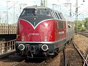
The most famous diesel-hydraulic locomotive is the German V 200, which were built from 1953 in a total number of 136. The only diesel-electric locomotives of the Deutsche Bundesbahn were BR 288 (V 188), of which 12 were built in 1939 by the Deutsche Reichsbahn. In the UK, the Western Region of British Rail bought a number of Diesel Hydraulic locomotives, ranging from small light duty freight locos to high powered mainline passenger locomotives, but these were withdrawn early due to being non standard, and also in some cases suffering from reliability problems (see below), being replaced by Diesel Electrics. A number were rescued for preservation though, and some are capable of running on the mainline.
The high reliability of the German locomotives was paralleled by higher reliability of non-German locomotives built with German-made parts compared to that of the same designs built using parts made locally to German patterns under licence. Much of the unreliability experienced outside Germany was due to poor quality control in the local manufacture of engines and transmissions. Another contributing factor was poor maintenance due to staff accustomed to steam locomotives now working on unfamiliar and much more complex designs in unsuitable conditions, and failing to follow the unit-replacement maintenance methods which were part of the German success. It is notable that diesel-hydraulic multiple units, with the advantages of modern manufacturing techniques and improved maintenance procedures, are now extremely successful in widespread use, achieving excellent reliability.
In the 1960s, more than 15 diesel-hydraulic locomotives were purchased by the Denver & Rio Grande and Southern Pacific Railroads on a trial basis from the Kraus-Maffei company. Only the outer shell of one of these (converted into a camera car by SP in the 1970s) exists today, the others having all been scrapped.
Diesel-steam
Diesel-steam locomotives can use diesel or steam power, as needed.
Multiple unit operation
Most Diesel locomotives are capable of multiple unit operation (MU) as a means of increasing horsepower and tractive effort when hauling heavy trains. All North American locomotives, including export models, use a standardised AAR electrical control system interconnected by a 27-pin jumper cable between the units. For UK built locomotives, a number of incompatible control systems are used, but the most common is the Blue Star system, which is electro-pneumatic and fitted to most early diesel classes. A small number of types, typically higher-powered locomotives intended for passenger only work, do not have multiple control systems. In all cases, the electrical control connections made common to all units in a consist are referred to as trainlines. The result is that all locomotives in a consist behave as one in response to the engineer's (driver's) control movements.
The ability to MU Diesel-electric locomotives was first introduced in the EMD FT four-unit demonstrator that toured the USA in 1939. At the time, American railroad work rules required that each operating locomotive in a train had to have on board a full crew. EMD circumvented that requirement by joining the cab-equipped "A" and cabless booster "B" units of the demonstrator set with drawbars instead of conventional knuckle couplers and declaring the set to be a single locomotive. Electrical interconnections were made so one engineer (driver) could operate the entire consist from the head-end unit. Later on, work rules were amended and the semi-permanent joining of units via drawbars was eliminated in favor of couplers, as servicing had proved to be somewhat cumbersome due to the total length of the consist (about 200 feet or nearly 61 meters).
In mountainous regions, it is common to interpose helper locomotives in the middle of the train, both to provide the extra power needed to ascend a grade and to limit the amount of stress applied to the draft gear of the car coupled to the head-end power. The helper units in such configurations are controlled from the lead unit's cab via coded radio signals. Although this is technically not MUing, the behavior is the same as with physically interconnected units.
References
- ↑ Diesel, Rudolf. U.S. Patent No. 608,845, filed July 15, 1895, and issued August 9, 1898 Accessed via Google Patent Search at: US Patent #608,845 on February 8, 2007.
- ↑ Churella, Albert J. (1998). From Steam to Diesel: Managerial Customs and Organizational Capabilities in the Twentieth-Century American Locomotive Industry. Princeton, New Jersey: Princeton University Press. pp. 15. ISBN 0-691-02776-5.
- ↑ Churella, page 12
- ↑ 4.0 4.1 Stover, John F. (1997). American Railroads. Chicago, Illinois: The University of Chicago Press. pp. 212. ISBN 0-226-77658-I.
- ↑ Edison, Thomas A. U.S. Patent No. 493,425, filed January 19, 1891, and issued March 14, 1891 Accessed via the Edison Papers at: US Patent #493,425 on February 8, 2007.
- ↑ Lemp, Hermann. U.S. Patent No. 1,154,785, filed April 8, 1914, and issued September 28, 1915. Accessed via Google Patent Search at: US Patent #1,154,785 on February 8, 2007.
- ↑ Churella, 25-27
- ↑ "Railroads To Try Diesel Locomotive", Special to the New York Times: 1, February 18, 1925
- ↑ Churella, 27
- ↑ Churella, 28-30
- ↑ Churella, 10
- ↑ Churella, 19
- ↑ Churella, 12-17
- ↑ 14.0 14.1 Stover, 213
- ↑ Churella, 14
See also
- Air brake (rail)
- Railway brakes
- Electric locomotive
- Hybrid locomotive
- List of British Rail classes