Rail tracks
| Rail gauge |
|---|
| Broad gauge |
| Standard gauge |
| Narrow gauge |
| Minimum gauge |
| List of rail gauges |
| Break-of-gauge |
| Dual gauge |
| Gauge conversion |
| Rail tracks |
| Tramway track |
| [edit] |

Rail tracks are used on railways (or railroads), which, together with railroad switches (or points), guide trains without the need for steering. Tracks consist of two parallel steel rails, which are laid upon sleepers (or cross ties) that are embedded in ballast to form the railroad track. The rail is fastened to the ties with rail spikes, lag screws or clips such as Pandrol clips.
The type of fastener depends partly on the type of sleeper, with spikes being used on wooden sleepers, and clips being used more on concrete sleepers.
Usually, a baseplate tie plate is used between the rail and wooden sleepers, to spread the load of the rail over a larger area of the sleeper. Sometimes spikes are driven through a hole in the baseplate to hold the rail, while at other times the baseplates are spiked or screwed to the sleeper and the rails clipped to the baseplate.
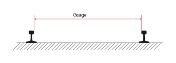
Steel rails can carry heavier loads than any other material. Railroad ties spread the load from the rails over the ground and also serve to hold the rails a fixed distance apart (called the gauge.)
Rail tracks are normally laid on a bed of coarse stone chippings known as ballast, which combines resilience, some amount of flexibility, and good drainage. Steel rails can also be laid onto a concrete slab (a slab track). Across bridges, track is often laid on ties across longitudinal timbers (referred to as "wheeltimbers" or "waybeams")[1] or longitudinal steel girders.
Contents |
Origins
- See also: Wagonway and Plateway
In the early years of railways, there was much experimentation with rails, sleepers and fixtures, before the better designs emerged.
Wooden rails with a metal strap on top were tried to save costs, but the straps had a tendency to come loose and penetrate the carriages going over them. These were commonly known as "snakeheads".
The "flangeway" was an early type of railway, the rails of which were equipped with a flange, while the locomotives and rolling stock that ran on it had wheels with plain rims. However switches/turnouts were very primitive, and high speeds could not be achieved, thus leading to the demise of the flangeway and the rise of today's "edgeway".
Barlow rail had a wide cross section to spread the load, but the rail itself tended to spread and go out of gauge. [2] There are some examples in the Powerhouse Museum in Sydney. [3] [4]
Brunel's Great Western Railway used longitudinal sleepers, with piles to hold the track down, but as the earthworks settled, the piles came to hold the track up. "Bridge Rail" was originally used; this is somewhat similar to Barlow rail mentioned above, only squarer and perhaps thicker. [5]
"Pole Roads" were used in past American logging operations in place of the more expensive standard railroad. They consisted of wooden poles laid end-to-end and parallel to each other in place of the steel rails. Locomotives and rolling stock on pole roads used concave wheels (double flanged) as opposed to the single flange used on most railway lines. Fordson tractors were often converted into pole road locomotives. The major setback to these lines was that the primitive (often home-made) locomotives tended to derail on curves.
Rail

Hot rolled steel in the profile (cross-section) of an asymmetrical I-beam is usually used as the surface on which railway wheels run.[6] Unlike some other uses of iron and steel, railway rails are subject to very high stresses and have to be made of very high quality steel alloy. It took many decades to improve the quality of the materials, including the change from iron to steel. For example, minor flaws in the steel that pose no problems in reinforcing rods for buildings can lead to broken rails and dangerous derailments when used on railway tracks. The heavier the rails and the rest of the trackwork, the heavier and faster the trains the track can carry.
Profiles of rail include:
- Bullhead rail
- Grooved rail
- Vignoles rail (flat-bottomed rail)
- Flanged T rail
Historically, North American railroads until the mid- to late-20th century used sections of rail that measured 39 ft (11.9 m) long so they could be carried to and from a worksite in 'gondola' cars, which often measured 40 feet (12.2 m) long; as gondola sizes increased, so did rail lengths.
Rail classification (weight)

Rail is graded by weight over a standard length. Heavier rail can support greater axle loads and higher train speeds without sustaining damage than lighter rail, but at a greater cost. In North America and the UK, rail is graded in units of pounds per yard (usually just shown as 'pound' or 'lb'), so "130-pound rail" would weigh 130 lb per linear yard (about 64 kg/m). The usual range is 115 to 141 lbs (about 57 to about 70 kg/m). In Europe, rail is graded in kg/m and the usual range is 40 to 60 kg/m (81 to 121 pounds per yard). The heaviest rail ever mass-produced was 155 pounds (about 77 kg/m) and was rolled for the Pennsylvania Railroad. The UK is in the process of transition from the imperial to metric rating of rail.
Joining rails
Rails are produced in fixed lengths and need to be joined end-to-end to make a continuous surface on which trains may run. The traditional method of joining the rails is to bolt them together using metal plates, producing what is known as jointed track. For more modern usage, particularly where higher speeds are required, the lengths of rail may be welded together to form continuous welded rail (CWR).
Jointed track


Jointed track is made using lengths of rail, usually around 20 metres (60 ft) long, bolted together using perforated steel plates known as fishplates (UK) or joint bars (North America).
Fishplates are usually 60 cm (2 ft) long, used in pairs either side of the rail ends and bolted together (usually four, but sometimes six bolts per joint). The bolts may be oppositely-oriented so that in the event of a derailment and a wheel flange striking the joint, only some of the bolts will be sheared, reducing the likelihood of the rails misaligning with each other and exacerbating the seriousness of the derailment. (This technique is not applied universally, British practice being to have all the bolt heads on the same side of the rail.) Small gaps known as expansion joints are deliberately left between the rail ends to allow for expansion of the rails in hot weather. The holes through which the fishplate bolts pass are oval to allow for movement with expansion.
British practice was always to have the rail joints on both rails adjacent to each other, while North American practice is to stagger them.
Because of the small gaps left between the rails, when trains pass over jointed tracks they make a "clickety-clack" sound. Unless it is well-maintained, jointed track does not have the ride quality of welded rail and is less desirable for high speed trains. However, jointed track is still used in many countries on lower speed lines and sidings, and is used extensively in poorer countries due to the lower construction cost and the simpler equipment required for its installation and maintenance.
A major problem of jointed track is cracking around the bolt holes, which can lead to the rail head (the running surface) breaking. This was the cause of the Hither Green rail crash which caused British Railways to begin converting much of its track to Continuous Welded Rail.
Insulated joints
Where track circuits exist for signalling purposes, insulated block joints are required. These compound the weaknesses of ordinary joints. Specially-made glued joints, where all the gaps are filled with epoxy resin, increase the strength again.
As an alternative to the insulated joint, audio frequency track circuits can be employed using a tuned loop formed in approximately 20 m of the rail as part of the blocking circuit. Another alternative is the axle counter, which can reduce the number of track circuits and thus the number of insulated rail joints required.
Continuous welded rail


Most modern railways use continuous welded rail (CWR), sometimes referred to as ribbon rails. In this form of track, the rails are welded together by utilising flash butt welding to form one continuous rail that may be several kilometres long, or thermite welding to repair or splice together existing CWR segments. Because there are few joints, this form of track is very strong, gives a smooth ride, and needs less maintenance; trains can travel on it at higher speeds and with less friction. Welded rails are more expensive to lay than jointed tracks, but have much lower maintenance costs. The first welded track was used in Germany in 1924 and the US in 1930[7] and has become common on main lines since the 1950s.
Flash butt welding is the preferred process which involves an automated track-laying machine running a strong electrical current through the touching ends of two unjoined pieces of rail. The ends become white hot due to electrical resistance and are then pressed together forming a strong weld. Thermite welding is a manual process requiring a reaction crucible and form to contain the molten iron. Thermite-bonded joints are also seen as less reliable and more prone to fracture or break.
Rails expand in hot weather and shrink in cold weather. Welded track has very few expansion joints and if no special measures are taken it could become distorted in hot weather and cause a derailment. Distortion due to heat expansion is known in North America as sun kink, and in Britain as buckling. In North America a rail broken due to cold-related contraction is known as a pull-apart. To avoid temperature-related movement, welded rails are laid on concrete or steel sleepers, which are so heavy they hold the rails firmly in place. Great attention is paid to compacting the ballast effectively, particularly the shoulder over the ends of the sleepers, to prevent them from moving. Even so, in extreme weather, foot patrols monitor sections of track known to be problematic.
After new segments of rail are laid, or defective rails replaced (welded-in), the rails are artificially stressed. The stressing process involves either heating the rails causing them to expand,[8] or stretching the rails with hydraulic equipment. They are then fastened (clipped) to the sleepers in their expanded form. This process ensures that the rail will not expand much further in subsequent hot weather. In cold weather the rails try to contract, but because they are firmly fastened, cannot do so. In effect, stressed rails are a bit like a piece of stretched elastic firmly fastened down.
Engineers try to heat the rail to a temperature roughly midway between the average extremes of hot and cold (this is known as the 'rail neutral temperature'). If temperatures reach outside normal ranges however, welded rail can buckle in a hotter than usual summer or can actually break in a colder than anticipated winter. In North America, because broken rails are typically detected by the signaling system; they are seen as less of a problem than heat kinks which are not detected. For this reason, and because it is harder to break a rail than displace the trackbed, CWR is usually installed at a temperature of 90 °F (32 °C), to cope with rail temperature extremes of nearly 120 °F (49 °C) in the summer sun.
Joints are used in continuously welded rail when necessary; instead of a joint that passes straight across the rail, producing a loud noise and shock when the wheels pass over it, two sections of rail are sometimes cut at a steep angle and put together with a gap between them - a breather switch (referred to in Britain as an expansion joint). This gives a much smoother transition yet still provides some expansion room.
Rail support (sleeper/tie)
A railroad tie (also called a cross-tie in North American usage, or a railway sleeper in British usage) is a rectangular object on which the rails are supported and fixed. The tie has two main roles: to transfer the loads from the rails to the track ballast and the ground underneath, and to hold the rails to the correct width apart (to maintain the rail gauge). They are generally laid transverse (at right-angles) to the rails.
Gauge

During the early days of rail there was considerable variation in the gauge used by different systems. Today, sixty percent of the world's railways use a gauge of 1,435 mm (4 ft 8½ in), which is known as the standard or international gauge. Gauges wider than standard gauge are called broad gauge, those smaller than standard narrow gauge. Some stretches of track are dual gauge, with three (or sometimes four) parallel rails in place of the usual two, to allow trains of two different gauges to share the same track.[9]
Fixing rail to sleepers/ties


There are several methods used to fasten rail to wooden sleepers. The worldwide standard type of rail used today is flat-bottomed rail (Vignoles rail), which has a flat base and can stand upright without support. A flat-bottomed rail has a cross-section like that of an upside-down 'T' and is usually held to the sleeper with a tie plate (baseplate), a metal plate attached to the sleeper; although for lower cost construction flat bottom rails can be laid directly onto the sleepers.
Modern sleepers can be made of reinforced concrete and pressed steel, with rubber pads inserted between the sleeper and rail. This is done for two reasons: to give a smoother ride and to prevent the sleeper from shorting the track circuit, a low voltage passed through the rails for signalling purposes. This is different from a "traction current," which powers electric trains.
Spikes
A rail spike is a large nail with an offset head that is used to secure rails or fishplates (or baseplates) to ties in the track. Spikes are driven into wooden sleepers either by hammering them with a spike hammer by hand, or in an automated fashion with a spiker.
Spikes are cheaper and simpler to install than other methods but can loosen if the tie rots, much more easily than the British chair (a type of baseplate) does. An alternate method is the use of large wood screws, also called lag screws.
Chairs
In traditional British practice, cast metal chairs were screwed to the sleepers, which took a style of rail known as bullhead that was somewhat figure-8 in cross-section — wider at top and bottom (known as the head and foot respectively) and smaller in the middle (the web). Keys (wedges of wood or sprung steel) were then driven in between chair and rail to hold it in place. This was common practice on British railways until the 1950s, but is now largely obsolete[10].
The idea behind bullhead rails was that because both the top and bottom of the rails were the same shape, when one side of the rail became worn, the rail could be turned over to the unused side, thus extending the rail's lifespan. However the bottom head turned out to get dented, rendering the original idea useless. Since the turnover requirement was no longer needed, bullhead rails came to have a flat base (narrower than flat-bottomed rail), and the top part has curved edges that fit the profile of the train wheels.
Clips
A variety of different types of heavy-duty clips are used to fasten the rails to the underlying baseplate, one common one being the Pandrol fastener (Pandrol clip), named after its maker, which is shaped like a sturdy, stubby paperclip.[1], [2] and [3]. Another one is the Vossloh Tension Clamp.[4]
Sleeperless track
In recent years, methods have been developed to put tracks on concrete without using conventional sleepers or track ballast. While this method's construction cost is high, this system is expected to have significantly lower maintenance cost than conventional tracks. It is mainly used on high-speed lines and in tunnels, where maintenance access is difficult and where the track is subject to fewer climatic stresses (such as rain and temperature fluctuation).
See Tubular Modular Track.
Track maintenance

Track needs regular maintenance to remain in good order, especially when high-speed trains are involved. Inadequate maintenance may lead to a "slow order" (North American terminology, a "slack" or speed restriction in the United Kingdom) being imposed to avoid accidents (see Slow zone). Track maintenance was at one time hard manual labour, requiring teams of labourers (US: gandy dancers, UK: platelayers or navvies), who used levers to force rails back into place on steep turns, correcting the gradual shifting caused by the centripetal force of passing trains. Currently, maintenance is facilitated by a variety of specialised machines.
The profile of the track is maintained by using a railgrinder.
Common maintenance jobs include spraying ballast with weedkiller to prevent weeds growing through and disrupting the ballast. This is typically done with a special weed killing train.
Over time, ballast is crushed or moved by the weight of trains passing over it, periodically requiring relevelling ("tamping") and eventually to be cleaned or replaced. If this is not done, the tracks may become uneven causing swaying, rough riding and possibly derailments.
Rail Inspections utilize nondestructive testing methods to detect internal flaws in the rails. This is done by using specially equipped HiRail trucks, inspection cars, or in some cases handheld inspection devices.
Rails must be replaced before the railhead profile wears to a degree that may trigger a derailment. Worn mainline rails usually have sufficient life to be used on a branch line, siding or stub afterwards and are "cascaded" to those applications.
The environmental conditions along railroad track create a unique railway ecosystem. This is particularly so in the United Kingdom where steam locomotives are no longer used and vegetation has not been trimmed back so thoroughly. This, however, creates a problem for operating steam-hauled heritage and charter trains on mainlines in prolonged dry weather.
U.S. track classes
- See also: Route availability, used within the United Kindom
In the United States, the Federal Railroad Administration has developed a system of classification for track quality.[11][12] The class of a section of track determines the running speed limits and the ability to run passenger trains.
| Track type | Freight train | Passenger |
|---|---|---|
| Excepted [us 1] | <10 mph (16 km/h) | not allowed |
| Class 1 | 10 mph (16 km/h) | 15 mph (24 km/h) |
| Class 2 | 25 mph (40 km/h) | 30 mph (48 km/h) |
| Class 3 | 40 mph (64 km/h) | 60 mph (97 km/h) |
| Class 4 [us 2] | 60 mph (97 km/h) | 80 mph (130 km/h) |
| Class 5 [us 3] | 80 mph (130 km/h) | 90 mph (140 km/h) |
| Class 6 | 110 mph (180 km/h) | |
| Class 7 [us 4] | 125 mph (201 km/h) | |
| Class 8 [us 5] | 160 mph (260 km/h) | |
| Class 9 [us 6] | 200 mph (320 km/h) | |
- ↑ Only freight trains are allowed to operate on Excepted track and they may only run at speeds up to 10 mph (16 km/h). Also, no more than five cars loaded with hazardous material may be operated within any single train. Passenger trains of any type are prohibited.
- ↑ Most mainline track, especially that owned by major railroads is Class 4 track
- ↑ The only Class 5 track operated by a freight railroad are parts of the BNSF Railway Chicago–Los Angeles mainline, the old Santa Fe main, upon which ATS equipped passenger trains such as Amtrak's Southwest Chief can operate at up to 90 mph (140 km/h). This is gradually being reduced to Class 4 as the train stop system is retired.
- ↑ Most of Amtrak's Northeast Corridor is Class 7 trackage.
- ↑ Portions of the Northeast Corridor are the only Class 8 trackage in North America allowing for 135 mph (217 km/h) and 150 mph (240 km/h) operation.
- ↑ There is currently no Class 9 trackage.
Curves
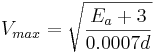
In addition to class, maximum track speed is also subject to specific regulatory restrictions known as rules. The rule governing the maximum permissible speed of a train operating on curved track is determined by the following formula:
![[3]](http://www.scalefour.org/resources/images/Pandrol1.jpg)
where  is the amount in inches that the outside rail is superelevated above the inside rail on a curve and
  is the degree of curvature in degrees per 100 feet (30 m).
  is given in miles per hour.

Track unbalanced superelevation in the U.S. is restricted to 3 inches (76 mm), though 4 inches (100 mm) is permissible by waiver. There is no hard maximum set for European railways, some of which have curves with over 11 inches (280 mm) of unbalanced superelevation to permit high-speed transportation.[13]
Generally the aim is for trains to run without flange contact, which also depends on the tyre profile of the wheels. Allowance has to be made for the different speeds of trains. Slower trains will tend to make flange contact with the inner rail on curves, while faster trains will tend to ride outwards and make contact with the outer rail. Either contact causes wear and tear and may lead to derailment. Many high-speed lines do not permit the use of slower freight trains, particularly with heavier axle loads. In some cases, the impact is reduced by the use of flange lubrication.
See also
|
|
References
- ↑ "MDA Railway Object Name Thesaurus". Retrieved on 2008-09-26.
- ↑ Light Railways October 2007 p13
- ↑ Digital Collections - Pictures - Lyell, Andrew R. Barlow rail [on the] Geelong - Melbourne line [Victoria], shilling [piece being used] as size contrast, 1930 - 19...
- ↑ Originally intended to rest directly on the ballast.
- ↑ Thame. Sections of GWR bridge rail covering a lineside drain at the eastern end of the station site. 11th May 2006. OS: SP715051 :: 077_Thame_110506b.JPG.jpg
- ↑ A Metallurgical History of Railmaking Slee, David E. Australian Railway History, February, 2004 pp43-56
- ↑ C. P. Lonsdale (September 1999). "Thermite Rail Welding: History, Process Developments, Current Practices And Outlook For The 21st Century" (PDF) (in English). Proceedings of the AREMA 1999 Annual Conferences 2. The American Railway Engineering and Maintenance-of-Way Association. Retrieved on 2008-07-06.
- ↑ "Continuous Welded Rail". Grandad Sez: Grandad's Railway Engineering Section. Retrieved on 2006-06-12.
- ↑ "message in the mailing list '1520mm' on Р75 rails".
- ↑ railwaysarchive.co.uk
- ↑ Federal Railroad Administration (2007-04-01). "Federal Railroad Administration Track Safety Standards Compliance Manual, Chapter 5 Federal Railroad Administration Track Safety Standards Compliance Manual" (PDF) (in English) 155. United States Government. Retrieved on 2008-04-21.
- ↑ Federal Railroad Administration (2007-04-01). "Federal Railroad Administration Track Safety Standards Compliance Manual, Chapter 6 Federal Railroad Administration Track Safety Standards Compliance Manual" (PDF) (in English) 101. United States Government. Retrieved on 2008-04-21.
- ↑ Zierke, Hans-Joachim. "Comparison of upgrades needs to recognize the difference in curve speeds". Retrieved on 2008-04-10.
Further reading
- Pike, J., (2001), Track, Sutton Publishing, ISBN 0-7509-2692-9
- Firuziaan, M. and Estorff, O., (2002), Simulation of the Dynamic Behavior of Bedding-Foundation-Soil in the Time Domain, Springer Verlag.
External links
- Table of North American tee rail (flat bottom) sections
- ThyssenKrupp handbook, Vignoles rail
- ThyssenKrupp handbook, Light Vignoles rail
- Track Details in photographs
|
|||||||||||||||||