Catenary

In physics and geometry, the catenary is the theoretical shape of a hanging flexible chain or cable when supported at its ends and acted upon by a uniform gravitational force (its own weight) and in equilibrium. The curve has a U shape that is similar in appearance to the parabola, though it is a different curve.
Contents |
History
The word catenary is derived from the Latin word catena, which means "chain". The curve is also called the "alysoid", "funicular", and "chainette". Galileo claimed that the curve of a chain hanging under gravity would be a parabola, but this was disproved by Jungius in a work published in 1669.[1]
In 1691, Leibniz, Christiaan Huygens, and Johann Bernoulli derived the equation in response to a challenge by Jakob Bernoulli. Huygens first used the term 'catenaria' in a letter to Leibniz in 1690, and David Gregory wrote a treatise on the catenary in 1690. However Thomas Jefferson is usually credited with the English word 'catenary'[2].
The application of the catenary to the construction of arches is ancient, as described below; the modern rediscovery and statement is due to Robert Hooke, who discovered it in the context of the rebuilding of St Paul's Cathedral[3], possibly having seen Huygen's work on the catenary. In 1671, Hooke announced to the Royal Society that he had solved the problem of the optimal shape of an arch, and in 1675 published an encrypted solution as a Latin anagram[4] in an appendix to his Description of Helioscopes,[5] where he wrote that he had found "a true mathematical and mechanical form of all manner of Arches for Building," He did not publish the solution of this anagram[6] in his lifetime, but in 1705 his executor provided it as:
| “ | Ut pendet continuum flexile, sic stabit contiguum rigidum inversum. | ” |
meaning
| “ | As hangs a flexible cable, so inverted, stand the touching pieces of an arch. | ” |
Euler proved in 1744 that the catenary is the curve which, when rotated about the x axis, gives the surface of minimum surface area (the catenoid) for the given bounding circle.[7]
Mathematical description
Equation
The equation (up to translation and rotation) of a catenary in Cartesian coordinates has the form
 ,
,
where  is the hyperbolic cosine function. The scaling factor
  can be interpreted as the ratio between the horizontal component of the tension on the chain (a constant) and the weight of the chain per unit of length.
The Whewell equation for the catenary is
 .
.
From this the Cesàro equation can be derived by differentiation:
 .
.
Derivation
Let  be the external force per unit length acting on a small segment of a chain, and let
  be the force of tension as a function of
  , the distance along the chain from some fixed point on it. The forces acting on the segment of the chain between
  and
and  are the force of tension
  at one end of the segment, the nearly opposite force
  at the other end, and the external force acting on the segment which is approximately
  . The chain is assumed to be in static equilibrium so these forces must balance, therefore
 .
.
Divide by  and take the limit as
  to obtain
 .
.
The flexibility of the chain implies that  is parallel to the curve of the chain, so we may assume
  where
where  is the unit tangent vector and
  is a scalar function of s.
We assume the chain has constant mass per unit length  and the only external force acting on the chain is that of a uniform gravitational field
  , so
, so  and
and
 .
.
Integrating,
 ,
,
where  and
and  are constants. By changing the point from which s is measured, we may take
  , so
, so
 .
.
If  is the tangential angle of the curve then
  is parallel to
  so
so
 .
.
Write  to combine constants and obtain the Whewell equation for the curve,
 .
.
The derivation of the curve for an optimal arch is similar except that the forces of tension become forces of compression and everything is inverted.
In general, parametric equations can be obtained from a Whewell equation by integrating:
To find these integrals, make the substitution  (or
(or  where
where  is the Gudermannian function). Then
  and
and

 .
.
We can eliminate u to obtain
where  and
and  are constants to be determined, along with
  , by the boundary conditions of the problem. Usually these conditions include two points from which the chain is being suspended and the length of the chain.
Other properties
A parabola rolled along a straight line traces out a catenary (see roulette) with its focus.
Square wheels can roll perfectly smoothly if the road has evenly spaced bumps in the shape of a series of inverted catenary curves. The wheels can be any regular polygon save for a triangle, but one must use the correct catenary, corresponding correctly to the shape and dimensions of the wheels [8].
A charge in a uniform electric field moves along a catenary (which tends to a parabola if the charge velocity is much less than the speed of light c).
Suspension bridges

Free-hanging chains follow the curve of the hyperbolic function above, but suspension bridge chains or cables, which are tied to the bridge deck at uniform intervals, follow a parabolic curve, much as Galileo originally claimed (derivation).
When suspension bridges are constructed, the suspension cables initially sag as the catenaric function, before being tied to the deck below, and then gradually assume a parabolic curve as additional connecting cables are tied to connect the main suspension cables with the bridge deck below.
The inverted catenary arch
The catenary is the ideal curve for an arch which supports only its own weight. When the centerline of an arch is made to follow the curve of an up-side-down (ie. inverted) catenary, the arch endures almost pure compression, in which no significant bending moment occurs inside the material. If the arch is made of individual elements (eg., stones) whose contacting surfaces are perpendicular to the curve of the arch, no significant shear forces are present at these contacting surfaces. (Shear stress is still present inside each stone, as it resists the compressive force along the shear sliding plane.) The thrust (including the weight) of the arch at its two ends is tangent to its centerline.

In antiquity, the curvature of the inverted catenary was intuitively discovered and found to lead to stable arches and vaults. A spectacular example remains in the Taq-i Kisra in Ctesiphon, which was once a great city of Mesopotamia. In ancient Greek and Roman cultures, the less efficient curvature of the circle was more commonly used in arches and vaults. The efficient curvature of inverted catenary was perhaps forgotten in Europe from the fall of Rome to the Middle-Ages and the Renaissance, where it was almost never used, although the pointed arch was perhaps a fortuitous approximation of it.

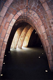
The Catalan architect Antoni Gaudí made extensive use of catenary shapes in most of his work. In order to find the best curvature for the arches and ribs that he desired to use in the crypt of the Church of Colònia Güell, Gaudí constructed inverted scale models made of numerous threads under tension to represent stones under compression. This technique worked well to solve angled columns, arches, and single-curvature vaults, but could not be used to solve the more complex, double-curvature vaults that he intended to use in the nave of the church of the Sagrada Familia. The idea that Gaudi used thread models to solve the nave of the Sagrada Familia is a common misconception, although it could have been used in the solution of the bell towers.

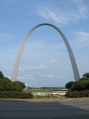
The Gateway Arch in Saint Louis, Missouri, United States follows the form of an inverted catenary. It is 630 feet wide at the base and 630 feet tall. The exact formula
is displayed inside the arch.
In structural engineering a catenary shell is a structural form, usually made of concrete, that follows a catenary curve. The profile for the shell is obtained by using flexible material subjected to gravity, converting it into a rigid formwork for pouring the concrete and then using it as required, usually in an inverted manner.
A kiln, a kind of oven for firing pottery, may be made from firebricks with a body in the shape of a catenary arch, usually nearly as wide as it is high, with the ends closed off with a permanent wall in the back and a temporary wall in the front. The bricks (mortared with fireclay) are stacked upon a temporary form in the shape of an inverted catenary, which is removed upon completion. The form is designed with a simple length of light chain, whose shape is traced onto an end panel of the form, which is inverted for assembly. A particular advantage of this shape is that it does not tend to dismantle itself over repeated heating and cooling cycles — most other forms such as the vertical cylinder must be held together with steel bands.
Anchoring of marine vessels
The catenary form given by gravity is made advantage of in its presence in heavy anchor rodes which usually consist mostly of chain or cable as used by ships, oilrigs, docks, and other marine assets which must be anchored to the seabed.
Particularly with larger vessels, the catenary curve given by the weight of the rode presents a lower angle of pull on the anchor or mooring device. This assists the performance of the anchor and raises the level of force it will resist before dragging. With smaller vessels and in shallow water it is less effective[9].
The catenary curve in this context is only fully present in the anchoring system when the rode has been lifted clear of the seabed by the vessel's pull, as the seabed obviously affects its shape while it supports the chain or cable. There is also typically a section of rode above the water and thus unaffected by buoyancy, creating a slightly more complicated curve.
Towed cables

When a cable is subject to wind or water flows, the drag forces lead to more general shapes, since the forces are not distributed in the same way as the weight. A cable having radius  and specific gravity
  , and towed at speed
  in a medium (e.g., air or water) with density
  , will have an
  position described by the following equations [10]:
Here  is the tension,
  is the incident angle,
  , and
, and  is the cable scope. There are three drag coefficients: the normal drag coefficient
  (
( for a smooth cylindrical cable); the tangential drag coefficient
  (
( ), and
  (
( ).
).
The system of equations has four equations and four unknowns:  ,
,  ,
,  and
and  , and is typically solved numerically.
Critical angle tow
Critical angle tow occurs when the incident angle does not change. In practice, critical angle tow is common, and occurs far from significant point forces.
Setting  leads to an equation for the critical angle:
If  , the formula for the critical angle becomes
or
or
leading to the rule-of-thumb formula
The drag coefficients of a faired cable are more complicated, involving loading functions that account for drag variation as a function of incidence angle.
Other uses of the term
- In railway engineering, a catenary structure consists of overhead lines used to deliver electricity to a railway locomotive, multiple unit, railcar, tram or trolleybus through a pantograph or a trolleypole. These structures consist of an upper structural wire in the form of a shallow catenary, short suspender wires, which may or may not contain insulators, and a lower conductive contact wire. By adjusting the tension in various elements the conductive wire is kept parallel to the centerline of the track, reducing the tendency of the pantograph or trolley to bounce or sway, which could cause a disengagement at high speed.
- In nonrigid and semi-rigid airships, a catenary curtain is a fabric and cable internal structure used to distribute the weight of the gondola across a large area of the ship's envelope.
- In conveyor systems, the catenary is the portion of the chain or belt underneath the conveyor that is traveling back to the start. It is the weight of the catenary that keeps tension in the chain or belt.
See also
References
- ↑ Swetz, Faauvel, Bekken, "Learn from the Masters", 1997, MAA ISBN 0883857030, pp.128-9
- ↑ "Catenary" at Math Words
- ↑ http://links.jstor.org/sici?sici=0035-9149(200105)55%3A2%3C289%3AMAMSTO%3E2.0.CO%3B2-X
- ↑ cf. the anagram for Hooke's law, which appeared in the next paragraph.
- ↑ Arch Design
- ↑ The original anagram was "abcccddeeeeeefggiiiiiiiiillmmmmnnnnnooprrsssttttttuuuuuuuux": the letters of the Latin phrase, alphabetized.
- ↑ http://mathworld.wolfram.com/Catenary.html
- ↑ "Roulette: A Comfortable Ride on an n-gon Bicycle" by Borut Levart, Wolfram Demonstrations Project, 2007.
- ↑ Chain, Rope, and Catenary - Anchor Systems For Small Boats
- ↑ A.P. Dowling, "The dynamics of towed flexible cylinders. Part 2. Negatively buoyant elements" (1988). Journal of Fluid Mechanics, 187, 533-571.
External links
- Eric W. Weisstein, Catenary at MathWorld.
- "Catenary" at Encyclopédie des Formes Mathématiques Remarquables
- "Catenary" at Visual Dictionary of Special Plane Curves
- Hanging With Galileo - mathematical derivation of formula for suspended and free-hanging chains; interactive graphical demo of parabolic vs. hyperbolic suspensions.
- Catenary Demonstration Experiment - An easy way to demonstrate the Mathematical properties of a cosh using the hanging cable effect. Devised by Jonathan Lansey
- Horizontal Conveyor Arrangement - Diagrams of different horizontal conveyor layouts showing options for the catenary section both supported and unsupported
- Catenary curve derived - The shape of a catenary is derived, plus examples of a chain hanging between 2 points of unequal height, including C program to calculate the curve.
- Cable Sag Error Calculator - Calculates the deviation from a straight line of a catenary curve and provides derivation of the calculator and references.


![T\frac{{d\phi }}{{ds}}=-\rho _{0}\left( {\sigma -1}\right) \pi a^{2}g\cos
\phi +\rho _{0}av^{2}\left[ {C_{D}\sin \phi +\pi C_{N}}\right] \sin \phi�;](/2009-wikipedia_en_wp1-0.7_2009-05/I/c3a805d91b4ee2b34f4e5dc048113989.png)


![\rho _{0}\left( {\sigma -1}\right) \pi a^{2}g\cos \phi =\rho _{0}av^{2}\left[
{C_{D}\sin \phi +\pi C_{N}}\right] \sin \phi .](/2009-wikipedia_en_wp1-0.7_2009-05/I/1a65ed8b72284b12dfacaab21f9cc728.png)


