Apollo spacecraft

The Apollo spacecraft was designed as part of the Apollo Program, by the United States in the early 1960s to land men on the moon before 1970 and return them safely to earth. This goal was set forth by President Kennedy after the first flight of the Mercury Space Program. The spacecraft was made up of multiple units or stages that worked together to perform the mission of landing on the moon and returning safely to earth. The main components of the Apollo spacecraft were (going from top to bottom) the launch escape system, the Command Module, the Service Module, the Lunar Module and the lunar module adapter. These stages together would sit atop the launch vehicle.
The principle was Lunar Orbit Rendezvous: A rocket would launch the spacecraft to the moon. The spacecraft would fly to the moon and orbit it. A smaller portion of the spacecraft would land on the moon and return to lunar orbit. Then a portion of the spacecraft would return to earth.
Launch vehicles: Little Joe II, Saturn I, Saturn IB, and Saturn V.
Contents |
Command Module (CM)
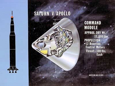
The Command Module was the control center for the Apollo spacecraft and living quarters for the crew. It contained the pressurized main crew cabin, crew couches, control and instrument panel, optical and electronic guidance systems, communications systems, environmental control system, batteries, heat shield, reaction control system, forward docking hatch, side hatch, five windows and the parachute recovery system.
Specifications
- Crew: 3
- Crew cabin volume: 6.17 m³
- Length: 3.47 m
- Diameter: 3.90 m
- Mass: 5,806 kg
- Structure Mass: 1,567 kg
- Heat Shield Mass: 848 kg
- RCS Mass: 400 kg
- Recovery Equipment Mass: 245 kg
- Navigation Equipment Mass: 505 kg
- Telemetry Equipment Mass: 200 kg
- Electrical Equipment Mass: 700 kg
- Communications Systems Mass: 100 kg
- Crew Couches and Provisions Mass: 550 kg
- Environmental Control System Mass: 200 kg
- Misc. Contingency Mass: 200 kg
- RCS Thrust: 12 x 420 N
- RCS Propellants: N2O4/UDMH
- RCS Engine Propellants: 75 kg
- RCS Specific Impulse Isp: 290 s (2.84 kN·s/kg)
- RCS Impulse: 257 kN·s
- Electric System Batteries: 20.0 kW·h, 1000 A·h
Service Module (SM)

The Service Module was a portion of the spacecraft that was unpressurized and contained fuel cells, batteries, high gain antenna, radiators, water, oxygen, hydrogen, reaction control system and propellant to enter and leave lunar orbit, and service propulsion systems. On Apollo 15, 16 and 17 it also carried a scientific instrument package, mapping camera and a small sub-satellite to study the moon.
A major portion of the service module was taken up by propellant and the main rocket engine that placed the Apollo spacecraft into and out of lunar orbit. The main rocket engine was also used for mid-course corrections between the earth and the moon. It was capable of multiple restarts. During Apollo 13, a tank heater thermostat fused closed, causing gases in an oxygen tank to vaporize and melted the casing on the wires to the tank stirring fan. During flight when the tank fan was turned on, a spark from short caused the gas to ignite. It remained attached to the Command Module throughout the mission. It was jettisoned just prior to reentry into the earth's atmosphere.
Specifications
- Length: 7.56 m
- Diameter: 3.90 m
- Mass: 24,523 kg
- Structure Mass: 1,910 kg
- Electrical Equipment Mass: 1,200 kg
- RCS Thrust: 16 × 440 N
- Propellants: N2O4/UDMH
- RCS Specific Impulse Isp: 290 s (2.84 kN·s/kg)
- RCS Impulse: 3,517 kN·s
- Service Propulsion Engine (SPS) Engine Mass: 3,000 kg
- SPS Engine Thrust: 98 kN
- SPS Engine Propellants: N2O4/Aerozine 50 (UDMH/N2H4)
- SPS Engine Propellants: 18,413 kg
- SPS Engine Specific Impulse Isp: 314 s (3.08 kN·s/kg)
- Spacecraft Delta-V: 2.804 km/s
- Electrical System: Fuel Cells
- Electric System: 6.30 average kW, 670 kW·h
Lunar Module (LM)

The Lunar Module was the portion of the Apollo spacecraft that landed on the moon and returned to lunar orbit and was the first true "spaceship" since it was designed to only fly in the vacuum of space. It is divided into two major parts, the Descent Module and the Ascent Module. It was designed specifically for flight in space. It supplied life support systems for two astronauts for a total of four to five days. The spacecraft was designed and manufactured by the Grumman Aircraft Company led by Tom Kelly.
The Descent Module contains the landing gear, landing radar antenna, descent rocket engine, and fuel to land on the moon. It also had several cargo compartments used to carry among other things, the Apollo Lunar Surface Experiment Packages ALSEP, Mobile Equipment Cart (a hand pulled equipment cart - Apollo 14) the Lunar Rover (moon car - Apollo 15, 16 and 17), surface television camera, surface tools and lunar sample collection boxes.
The Ascent Module contains the crew cabin, instrument panels, overhead hatch/docking port, forward hatch, optical and electronic guidance systems, reaction control system, radar and communications antennas, ascent rocket engine and fuel to return to lunar orbit and rendezvous with the Apollo Command and Service Modules.
Specifications
Ascent Stage
- Crew: 2
- Crew cabin volume: 6.65 m³
- Height: 3.54 m
- Diameter: 4.27 m
- Ascent Stage Mass: 4,547 kg
- Ascent Engine Propellants: 2,358 kg
- RCS Thrust: 16 × 440 N
- RCS Propellants: N2O4/UDMH
- RCS Specific Impulse Isp: 290 s (2.84 kN·s/kg)
- Ascent Engine Thrust: 16 kN
- Ascent Engine Propellants: N2O4/Aerozine 50 (UDMH/N2H4)
- Ascent Engine Isp: 311 s (3.05 kN·s/kg)
- Ascent Stage Delta-V: 2.22 km/s
- Electric Batteries: 28-32V; two 296 A-h, 56.7 kg each
Descent Stage
- Height: 2.83 m
- Diameter: 4.21 m
- Landing Gear Diameter: 9.37 m
- Descent Stage Mass: 10,149 kg
- Descent Engine Propellants: 8,165 kg
- Descent Engine Thrust: 44 kN
- Descent Engine Propellants: N2O4/Aerozine 50 (UDMH/N2H4)
- Descent Engine Engine Specific Impulse Isp: 311 s (3.05 kN·s/kg)
- Descent Stage Delta-V: 2.47 km/s
- Electric Batteries: 28-32V; four (Apollo 9-14) or five (Apollo 15-17) 415 A-h; 61.2 kg each
Launch Escape System (LES)

- See also: Apollo abort modes
The purpose of the Apollo launch escape system was to pull the Command Module (which contained the crew cabin) away from the launch vehicle in an abort situation.
The emergency could be a pad fire, exploding launch vehicle or a launch vehicle going off course.
The Launch Escape System would work automatically (or through manual activation) to fire a solid fuel escape rocket and open a canard system to direct the Command Module away from, and off the path of, a launch vehicle in trouble. The Launch Escape System would then jettison and the Command Module would land with its parachute recovery system.
If the emergency happened on the launch pad, the Launch Escape System would lift the Command Module to a sufficient height to allow the recovery parachutes to deploy safely before coming in contact with the ground.
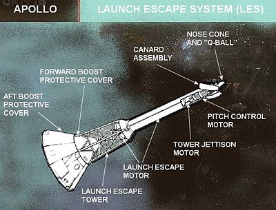
Major Components of the Launch Escape System (LES)
- Nose Cone and Q-Ball—The nosecone of the LES contained sensors to sense aerodynamic pressure ("Q"), and thereby determine the angle of attack, airspeed, and attitude of the spacecraft and launch vehicle. This structure, known as the Q-ball[1], relayed this information to the command module and the launch vehicle guidance system.
- Q-Ball cover—The Q-ball's pitot tubes, which could easily be clogged by debris, were protected by a styrofoam cover that was removed a few seconds before launch.[2] The Q-ball cover was split in half vertically and held together by a 2-inch (51 mm) rubber band. A razor blade was positioned behind the rubber band, pinched between the halves of the cover. A wire rope was connected to the top and bottom of the razor blade and to both halves of the cover. The wire rope was routed through a pulley on the hammerhead crane at the top of the launch umbilical tower (LUT) down to a tube on the right side of the 360-foot (110 m) level of the LUT. The wire rope was connected to a cylindrical weight inside a tube. The weight rested on a lever controlled by a pneumatic solenoid valve. When the valve was actuated from the Launch Control Center (LCC), the pneumatic pressure of 600 PSI GN2 (nitrogen gas) rotated the lever down allowing the weight to drop down the tube. The dropping weight pulled the wire rope, which pulled the blade cutting the rubber band, and the wire rope pulled the halves of the Q-Ball away from the launch vehicle. The apparent overengineering of this simple system was due to the fact that the launch escape system, which depended on the Q-ball data, was armed 5 minutes before launch, so retraction of the Q-ball cover was a life-critical part of a possible pad abort.
- Canard Assembly and Pitch Motor—These worked in combination to direct the Command Module off a straight path and to the side during an emergency. This would direct the Command Module off the flight path of an exploding launch vehicle. It would also direct the Command Module to land off to the side of any launch pad fire and not in the middle of it.
- Tower Jettison Motor—A smaller solid fuel motor that jettisons the Launch Escape System after it is no longer needed. This usually happens after second stage ignition.
- Launch Escape Motor—The main solid fuel rocket motor that, firing through four rocket nozzles, pulls the Command Module rapidly away from a launch emergency.
- Launch Escape Tower—Assembly that attaches the Launch Escape System rocket motors to the Command Module.
- Boost Protective Cover—Hollow conical structure that fits over the Command Module during launch. It protects the Command Module heat shield and windows during ascent through the atmosphere. It also protects the Command Module from rocket exhaust should the Launch Escape System have to be used.
Specifications
Abort Tests
- Pad Abort Test-1—Launch Escape System (LES) abort test from launch pad with Apollo Boilerplate BP-6.
- Pad Abort Test-2—LES pad abort test of near Block-I CM with Apollo Boilerplate B-23A.
- Little Joe II—In-air LES abort tests.
Spacecraft Lunar Module Adapter (SLA)

The Spacecraft Lunar Module Adapter (SLA) was a conical aluminum structure which supported the Service Module above the Saturn S-IVB rocket stage. It protected the Lunar Module, the Service Propulsion System engine nozzle, and the launch vehicle to Service Module umbilical during launch and ascent through the atmosphere.
The SLA was composed of four fixed seven foot long panels bolted to the Instrument Unit on top of the S-IVB stage, which were connected via hinges to four twenty-one foot long panels which would open from the top similar to flower petals.
The SLA was made from 1.7 inch (42.5 mm) thick aluminum honeycomb material.[3] The exterior of the SLA was covered by a thin (0.03–0.2 inch, 1–5 mm) layer of cork and painted white to minimize thermal stresses during launch and ascent.[4]
The Service Module was bolted to a flange at the top of the longer panels, and power to the SLA multiply-redundant pyrotechnics was provided by an umbilical. Because a failure to separate from the S-IVB stage could leave the crew stranded in orbit, the separation system used multiple signal paths, multiple detonators and multiple explosive charges where the detonation of one charge would set off another even if the detonator on that charge failed to function.
Once in space, the astronauts pressed the 'CSM/LV Sep' button on the control panel to separate the Command and Service Module from the launch vehicle. Detonating cord was ignited around the flange between the Service Module and SLA, and along the joints between the four SLA panels, releasing the Service Module and blowing apart the connections between the panels. Dual-redundant pyrotechnic thrusters at the lower end of the SLA panels then fired to rotate them around the hinges at 30-60 degrees per second.
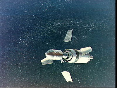
On the Apollo 7 flight the SLA panels were retained on the S-IVB, but concerns about collision between the CSM and the SLA panels when docking with the Lunar Module led to a decision that the Saturn V launches would release the panels during the separation process. When they opened to an angle of approximately 45 degrees the hinges connecting the moving panels to the fixed panels disengaged, and springs pushed the panels away from the S-IVB at a velocity of around five miles per hour. Hence by the time the astronauts had rotated the Command/Service Module through one hundred and eighty degrees in preparation for docking, the panels were a safe distance away with no chance of a collision occurring.
The Lunar Module was connected to the SLA at four points around the lower panels. After the astronauts docked the CSM to the LEM, they blew charges to separate those connections and a guillotine severed the LEM to Instrument Unit umbilical. After the charges fired, springs pushed the LEM away from the S-IVB and the astronauts were free to continue their trip to the Moon.
Specifications
- Height: 8.5 m (28 ft)
- Apex Diameter: 3.9 m (12 ft 10 in) Service Module end
- Base Diameter: 6.6 m (21 ft 8 in) S-IVB end
- Weight: 1,837 kg (4,050 lb)
- Volume: 190 m³ (6,700 ft³), 140 m³ (5,000 ft³) usable
Abort modes
- Apollo abort modes
- Pad Abort Test-1 - Launch Escape System (LES) abort test from launch pad with Apollo Boilerplate BP-6.
- Pad Abort Test-2 - LES pad abort test of near Block-I CM with Apollo Boilerplate B-23A.
Current locations of Command and Lunar Modules
AS-202 Command Module - USS Hornet, Alameda, California
Apollo 1 Command Module - Langley Research Center, Hampton, Virginia
Apollo 5 Lunar Module - Burned up in Earth's atmosphere
Apollo 6 Command Module - Fernbank Science Center, Atlanta, Georgia
Apollo 7 Command Module - Frontiers of Flight Museum, Dallas, Texas
Apollo 8 Command Module - Museum of Science and Industry (Chicago), Chicago, Illinois
Apollo 9 Command Module "Gumdrop" - San Diego Aerospace Museum, San Diego, California
Apollo 9 Lunar Module "Spider" -Burned up in Earth's atmosphere
Apollo 10 Command Module "Charlie Brown" - Science Museum, London, England
Apollo 10 Lunar Module "Snoopy" - Descent stage jettisoned, impacted moon, site unknown; ascent stage in heliocentric orbit
Apollo 11 Command Module "Columbia" - National Air and Space Museum, Washington, D.C.
Apollo 11 Lunar Module "Eagle" - Descent stage on moon; ascent stage jettisoned from Columbia on July 21, 1969 at 23:41 UT, impact site unknown
Apollo 12 Command Module "Yankee Clipper" - Virginia Air and Space Center, Hampton, Virginia
Apollo 12 Lunar Module "Intrepid" - Descent stage on moon; ascent stage impacted Moon on November 20, 1969 at 22:17:17.7 UT 3.94 S, 21.20 W
Apollo 13 Command Module "Odyssey" - Kansas Cosmosphere and Space Center, Hutchinson, Kansas
Apollo 13 Lunar Module "Aquarius" -Burned up in Earth's atmosphere
Apollo 14 Command Module "Kitty Hawk" - Astronaut Hall of Fame, Titusville, Florida
Apollo 14 Lunar Module "Antares" - Descent stage on moon; ascent stage impacted Moon on February 7, 1971 at 00:45:25.7 UT 3.42 S, 19.67 W
Apollo 15 Command Module "Endeavor" - National Museum of the United States Air Force, Wright-Patterson Air Force Base, near Dayton, Ohio
Apollo 15 Lunar Module "Falcon" - Descent stage on moon; ascent stage impacted Moon on August 4, 1971 at 03:03:37.0 UT 26.36 N, 0.25 E
Apollo 16 Command Module "Casper" - U.S. Space & Rocket Center, Huntsville, Alabama
Apollo 16 Lunar Module "Orion" - Descent stage on moon; ascent stage jettisoned on April 24, 1972, loss of attitude control made targeted impact impossible, impact site unknown
Apollo 17 Command Module "America" - NASA Johnson Space Center, Houston, Texas
Apollo 17 Lunar Module "Challenger" - Descent stage on moon; ascent stage impacted Moon on December 15, 1972 at 06:50:20.8 UT 19.96 N, 30.50 E
Apollo-Soyuz Command Module - California Science Center, Los Angeles, California
Apollo-Soyuz Test Command Module - Kennedy Space Center, Merritt Island, Florida
Skylab 2 / Crew 1 Command Module - National Museum of Naval Aviation, Pensacola, Florida
Skylab 3 / Crew 2 Command Module - NASA John H. Glenn Research Center at Lewis Field, Cleveland, Ohio
Skylab 4 / Crew 3 Command Module - National Air and Space Museum, Washington, D.C.
Note 1: The service modules for all Apollo spacecraft were jettisoned before earth re-entry, so all have burned up in the earth's atmosphere.
Note 2: Lunar orbits are generally unstable, so spacecraft jettisoned in lunar orbit would eventually impact the moon. However, the impact sites would be unknown.
References
- North American Rockwell, 'Apollo Command Module News Reference', 1968.
- NASA TN D-7083: Launch Escape Propulsion Subsystem
- Apollo Operations Handbook Lunar Module Subsystems Data